Overview
In this project, we implemented computing vertex locations for Bezier curves as well as surfaces with the de Casteljau algorithm. We also implemented Loop subdivision. In doing so we learned how to navigate the half-edge mesh data structure and worked with mesh processing techniques. In order to accomplish subdivision we implemented edge flip and edge split operations, which improve the appearance of a mesh. All of these operations can help create and refine meshes.
Section I: Bezier Curves and Surfaces
Part 1: Bezier Curves with 1D de Casteljau Subdivision
Briefly explain de Casteljau's algorithm and how you implemented it in order to evaluate Bezier curves.De Casteljau's algorithm starts with n control points and produces a degree n-1 Bezier curve. This is accomplish by creating multiple layers of control points by linearly interpolating between consecutive pairs on control points (t indicates how far we move along the control points and thus determines the final position we are computing on the Bezier curve). After n-1 iterations of linearly interpolating layers of points, the algorithm will converge to single control point. This final control point will be on the Bezier curve.
Take a look at the provided .bzc files and create your own Bezier curve with 6 control points of your choosing. Use this Bezier curve for your screenshots below.
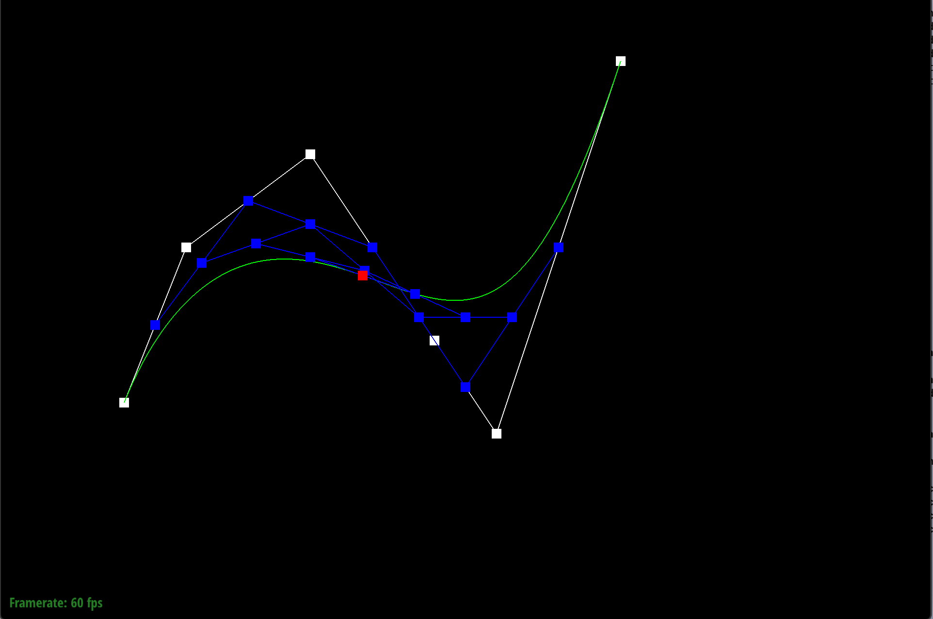
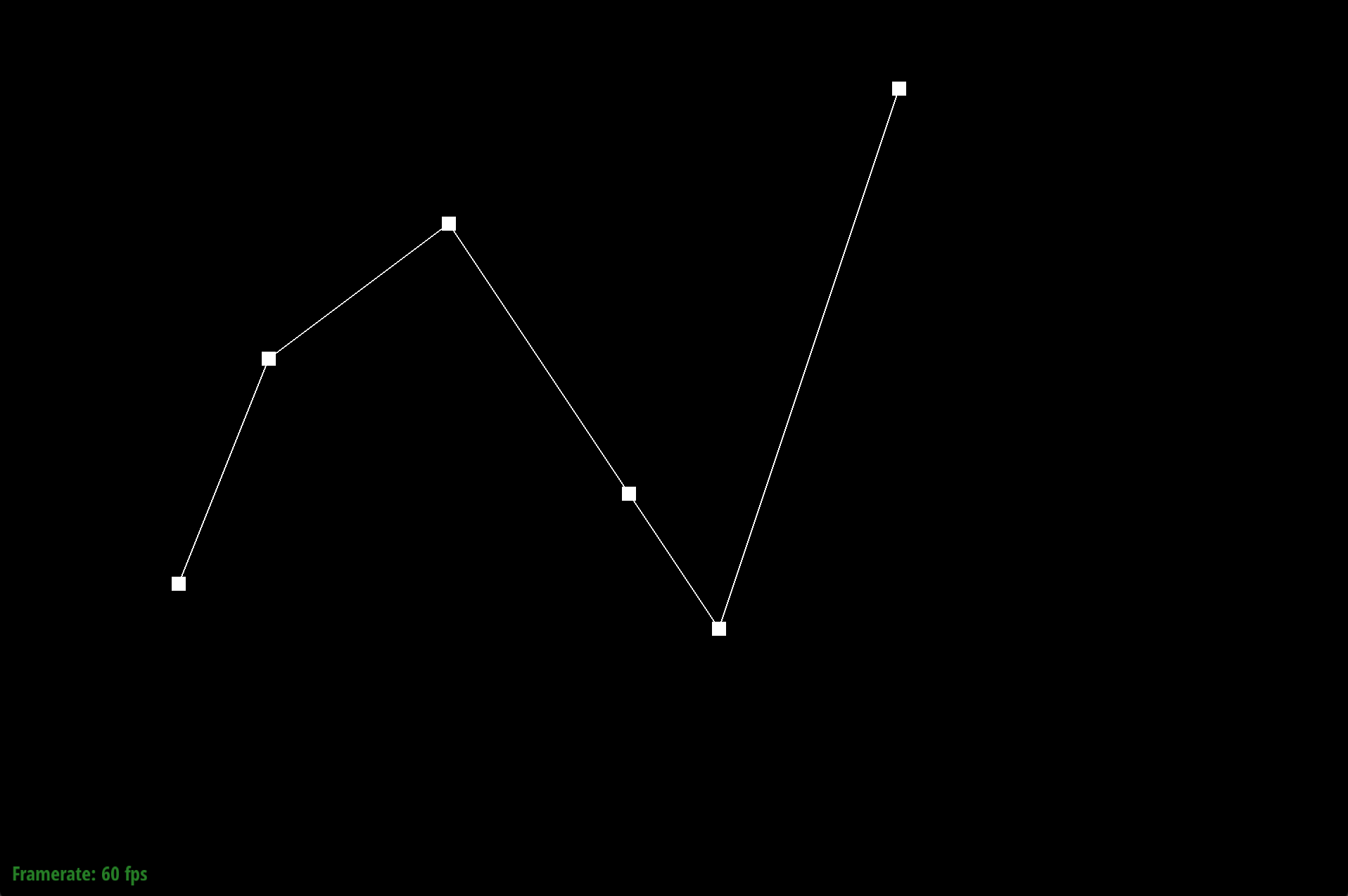
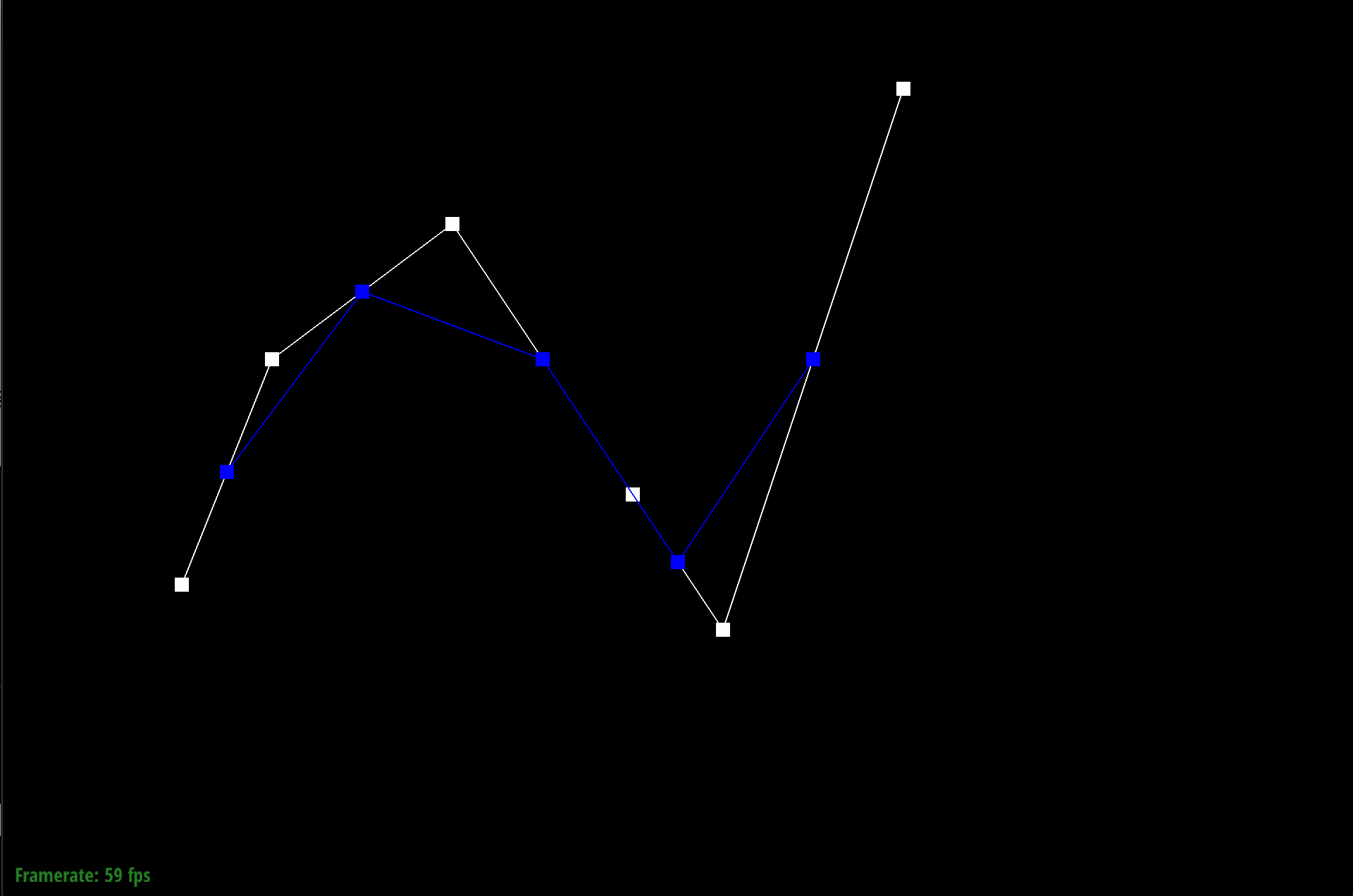
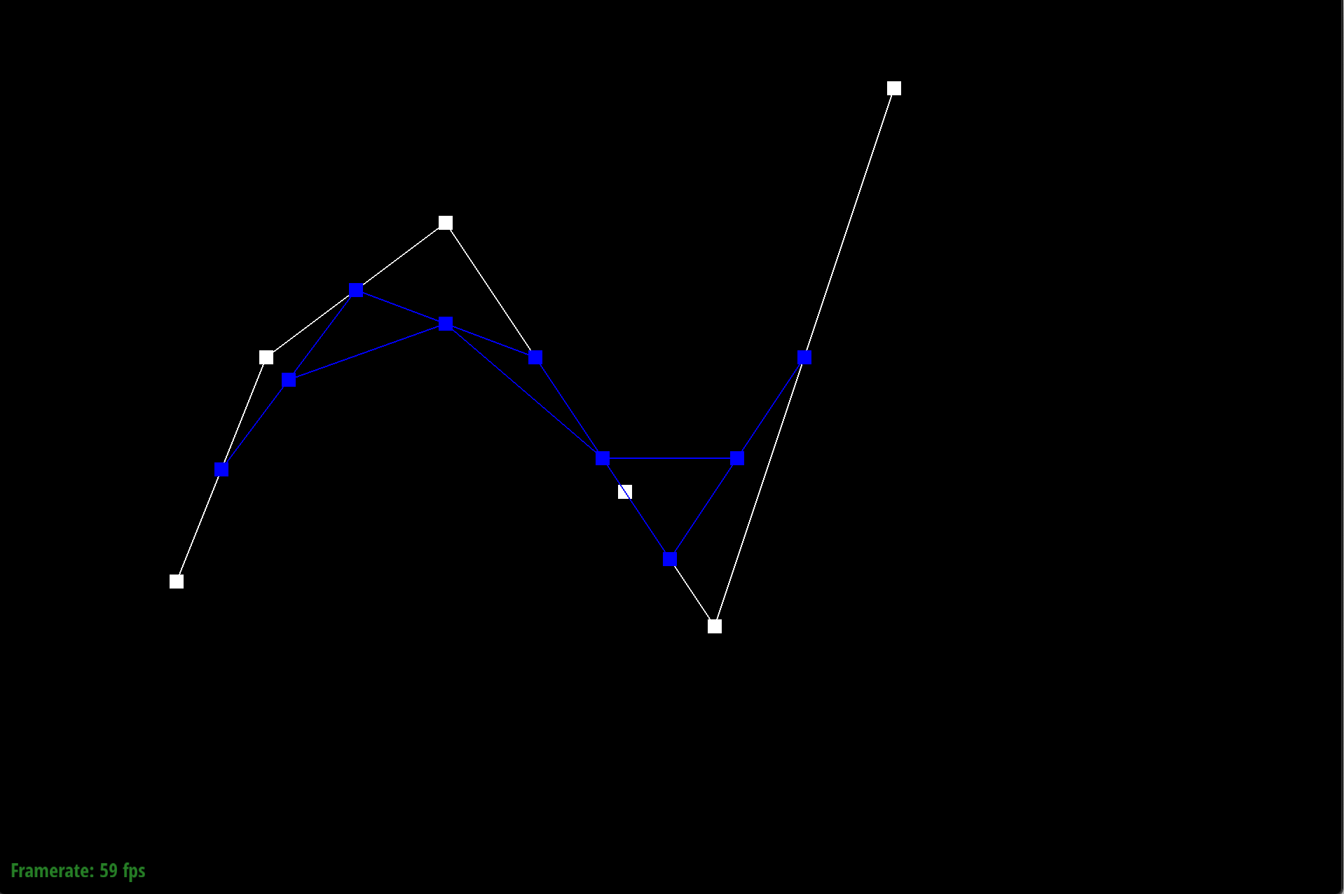
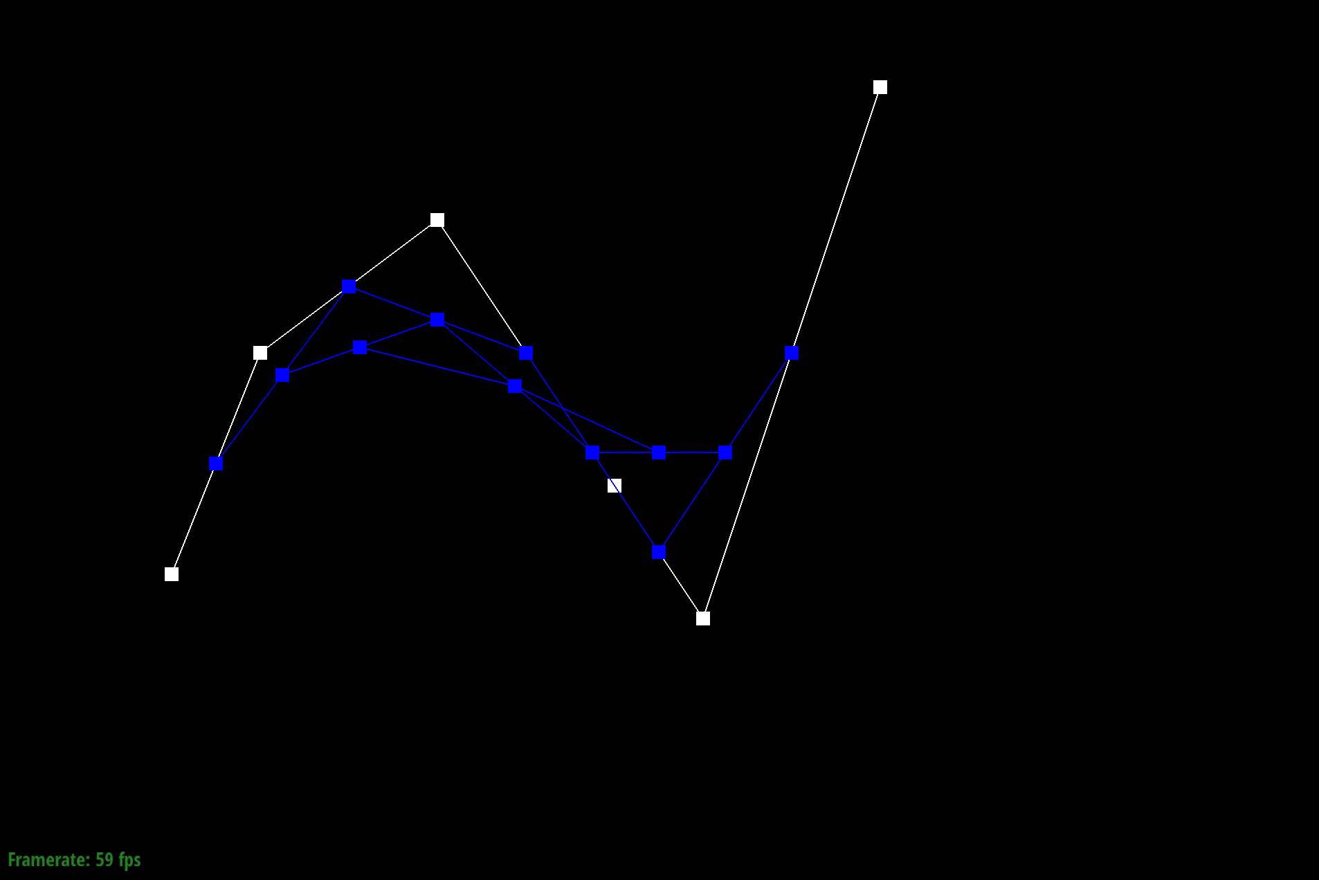
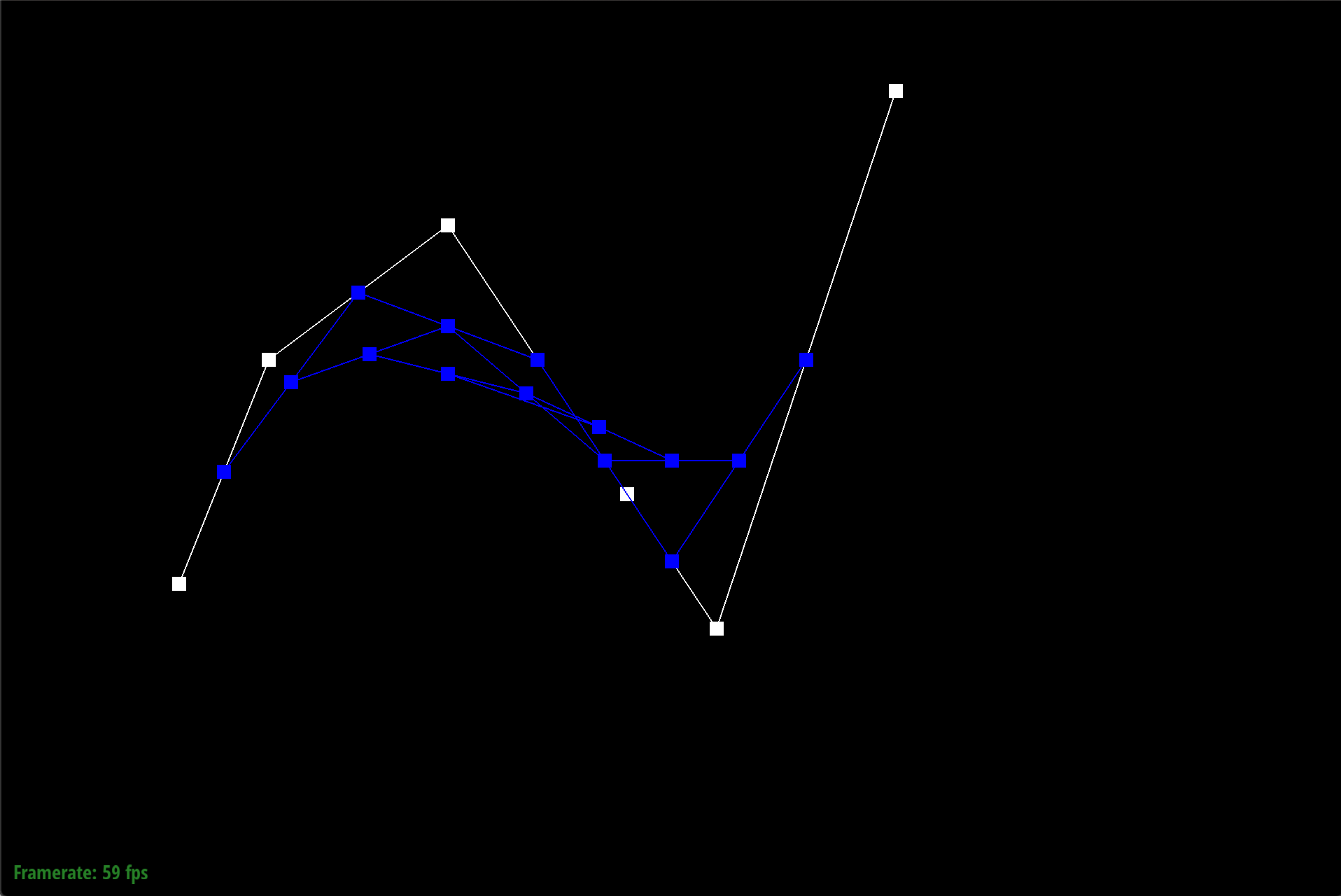
Show screenshots of each step / level of the evaluation from the original control points down to the final evaluated point. Press E to step through. Toggle C to show the completed Bezier curve as well.
|
|
|
|
|
Show a screenshot of a slightly different Bezier curve by moving the original control points around and modifying the parameter \(t\) via mouse scrolling.
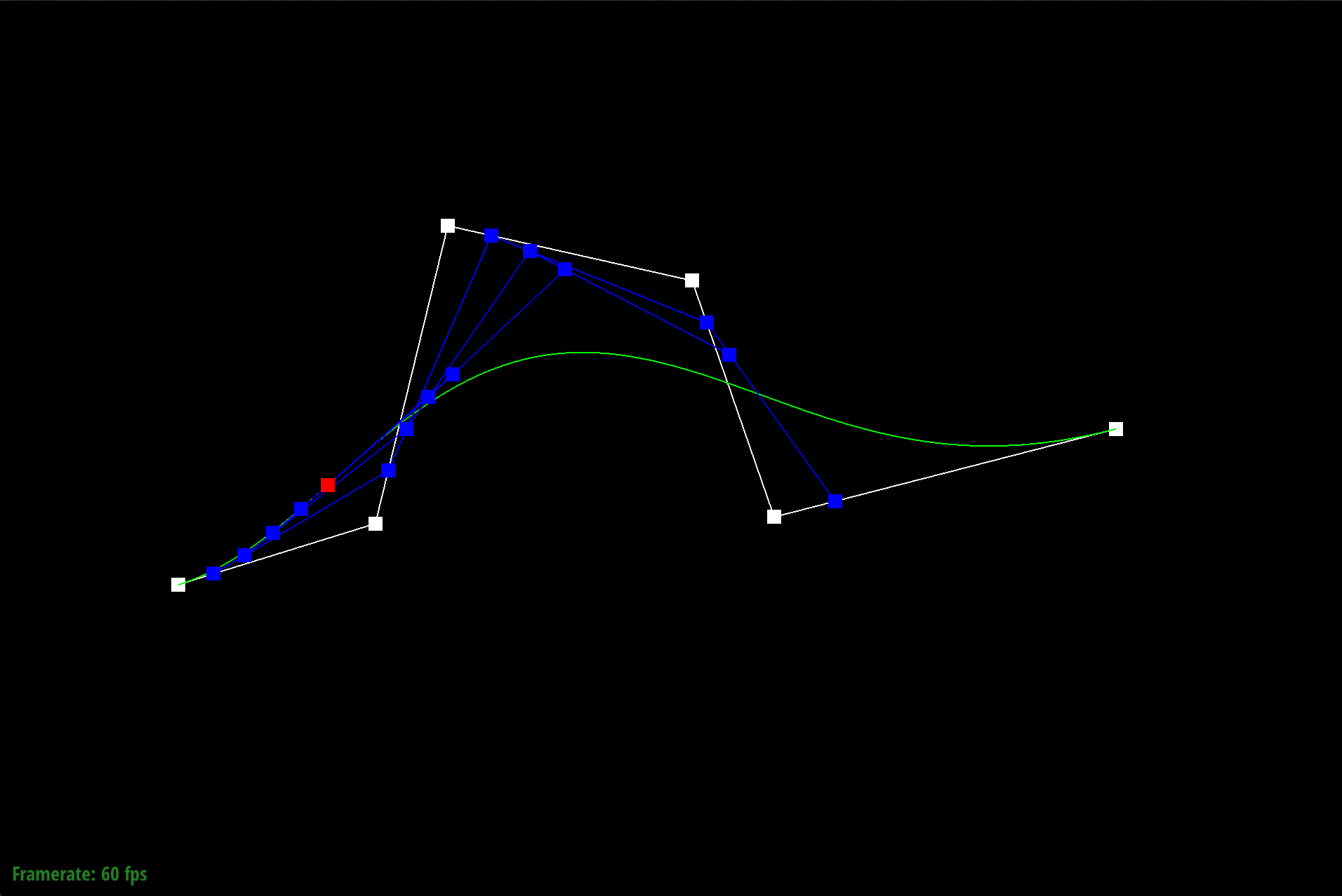
With an extremely small t parameter, we see that each intermediate point is weighted more towards the left, causing the final evaluated point to be on the left side of the curve, in contrast to the original t=0.5 value that made the evaulated point near the middle of the curve.
Part 2: Bezier Surfaces with Separable 1D de Casteljau
Briefly explain how de Casteljau algorithm extends to Bezier surfaces and how you implemented it in order to evaluate Bezier surfaces.We apply de Casteljau's algorithm to surfaces by first iterating through each row and then computing a series of n 1D Bezier curves. This will determine a set of n points, one for each row of the surface. Then we use these n points as control points to compute a Bezier curve along the column direction. This allows us to extend the Bezier curve logic to surfaces. We use u to determine how far to move along the rows and v to determine how far to move along the curve in the column direction.
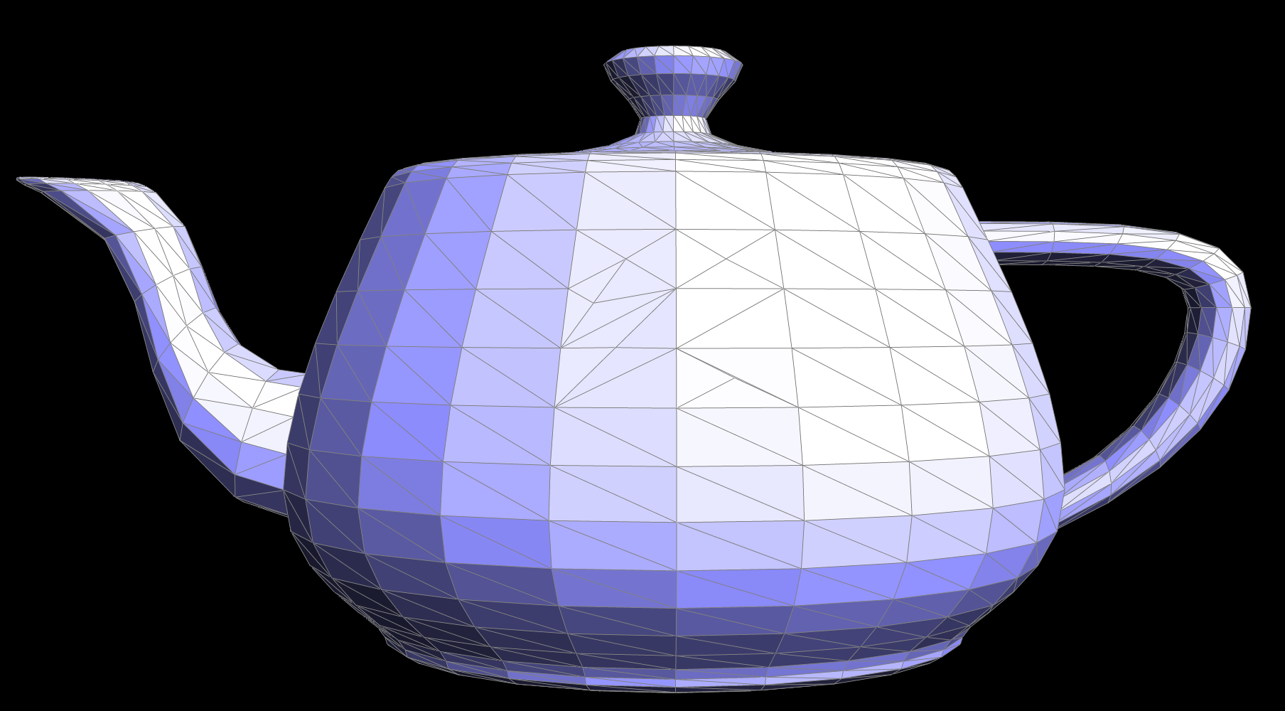
Show a screenshot of bez/teapot.bez (not .dae) evaluated by your implementation.
Section II: Triangle Meshes and Half-Edge Data Structure
Part 3: Area-Weighted Vertex Normals
Briefly explain how you implemented the area-weighted vertex normals.We create a do-while loop to iterate through the faces adjacent to the vertex. We do this by moving along half edges of the triangle and processing one face per iteration of the loop. The magnitude of the cross product between two edges on the face of the triangle is proportional to the triangle's area. We then add the un-normalized cross product to a running sum for every face. Once we have processed all faces we can normalize and return the result.
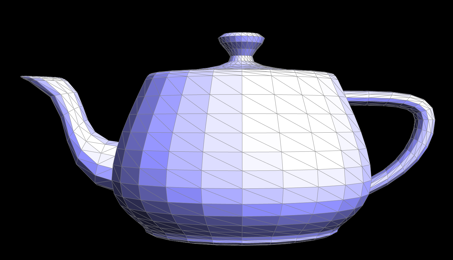
Show screenshots of dae/teapot.dae (not .bez) comparing teapot shading with and without vertex normals. Use Q to toggle default flat shading and Phong shading.

|
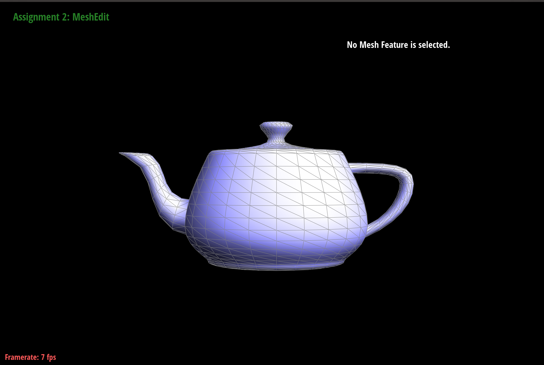
|
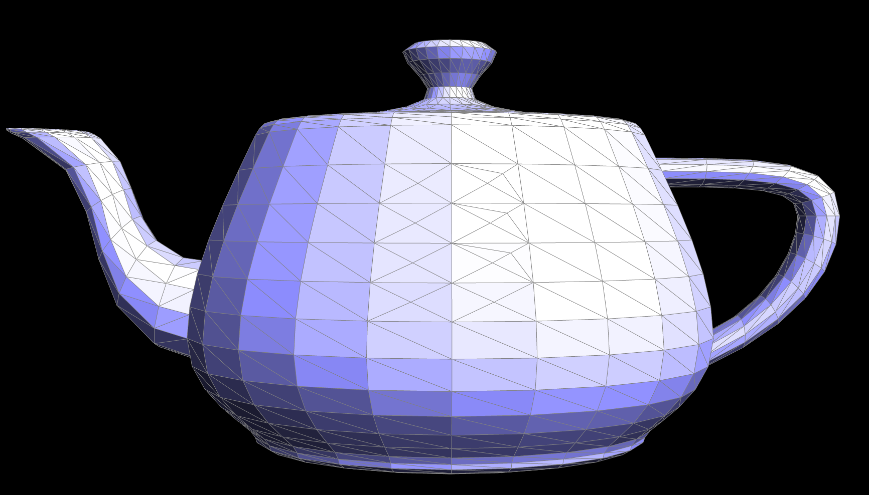
Part 4: Edge Flip
Briefly explain how you implemented the edge flip operation and describe any interesting implementation / debugging tricks you have used.We started off this implementation by carefully going through the example edge flip given in the spec. For every vertex, edge, halfedge, and face, we wrote down explicitly all the fields before and after the flip to determine which fields of each struct needed to be modified. Then we generalized these changes to the function to the given edge e0. Through walking through our example, we determined that we mainly needed to change the Halfedge struct and the halfedge field of Face and Vertex (the Edge struct could be left alone). One issue we came across was we found that there were holes in the teapot after flipping, and that was because we forgot to change the halfedge fields of the vertices. When flipping some vertical edges, one of the triangles ended up being darker than the other and looking slightly inverted, which is the degenerate case mentioned in the spec.
|
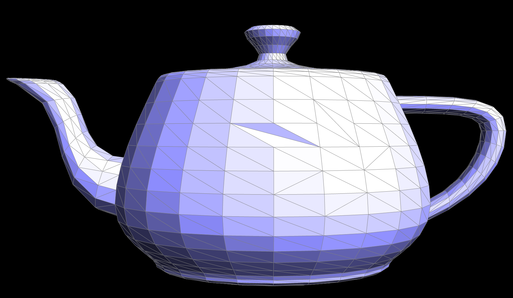
|
Write about your eventful debugging journey, if you have experienced one.
Our debugging journey mainly consisted of going back to our detailed walkthrough of the given example and checking every single field of each struct to see if we made a small error. This helped us realize we completely forgot to re-assign the halfedge field of the vertices. We were also initially concerned with why a vertical flip would result in a darker shading in one of the triangles and spent some time debugging that issue until we realized that was actually the expected output (degenerate case).
Part 5: Edge Split
Briefly explain how you implemented the edge split operation and describe any interesting implementation / debugging tricks you have used.We started this implementation by drawing out a before and after diagram and labeling all new vertices, halfedges, edges, and faces. This required creating 1 new vertex, 2 new faces, 3 new edges, and 6 new half edges. We converted the original e0 edge (cb in the example) to be one of the new edges (cm in the example). Then we went through each struct and reassigned the necessary fields. For example, the original edges now point to new halfedges, the faces and vertex structs also point to new half edges, and all halfedges required a call to setNeighbors to update all its fields.
Show screenshots of a mesh before and after some edge splits.

|
|
Show screenshots of a mesh before and after a combination of both edge splits and edge flips.

|
|
Write about your eventful debugging journey, if you have experienced one.
Initially our program kept freezing after attempting to split, so we relied on the "check_for" function to verify the fields of our half edges. We found that one of our halfedges did not have a "next" field which led us to see that we had a very small typo of passing in "md" instead of "ma" to the "next" parameter of a setNeighbor call.
If you have implemented support for boundary edges, show screenshots of your implementation properly handling split operations on boundary edges.
YOUR RESPONSE GOES HERE
Part 6: Loop Subdivision for Mesh Upsampling
Briefly explain how you implemented the loop subdivision and describe any interesting implementation / debugging tricks you have used.We tackled loop division by implementing it step by step. Starting with calculating the new (original) vertex positions and storing it in the Vertex structs, then calculating the newly created vertices' positions and storing them in the Edge struct. In order to distinguish between the black and blue edges (as described in the spec as black = edges part of the original mesh), we had to add a new field "isBlack" into the Edge struct. This helped us with the issue of splitting edges that were new (oversplitting), in addition to helping us figure out which edges connected a new and old vertex AND were not a part of the original mesh. Because of the way we chose to initialize the "isNew" fields of Edges and Vertices, and how we updated them in splitEdge, we found that it was necessary to correctly implement steps 3 and 4 by choosing the correct edges to split.
One of the main issues we kept running into while implementing this task was that the new vertex being created during edge splits and edges that were a part of different edge splits had fields that kept being overridden. We mainly used print statements throughout our edgeSplit function (which we had to keep modifying throughout task 6) to track when those fields were changing and which function was the cause of it. Another debugging trick we used was to comment out parts of our code (i.e. step 3-5) and manually flip/split the edges to see what the expected intermediate output was going to be, and slowly uncomment out parts of the code to isolate which part of the function was causing the issue.
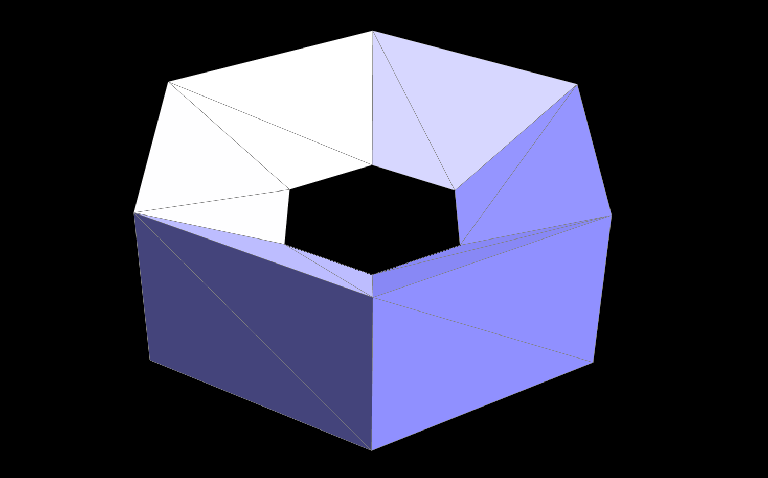
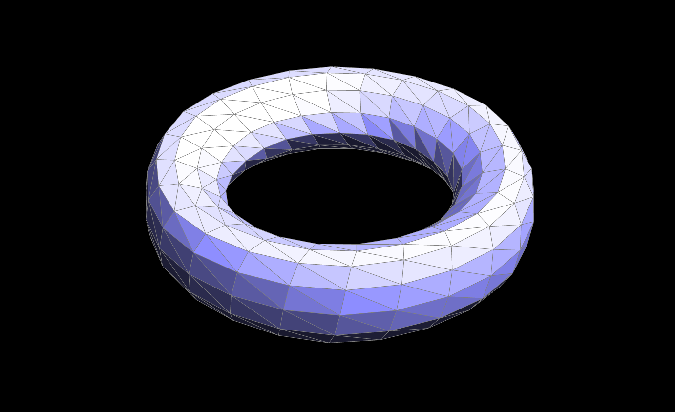
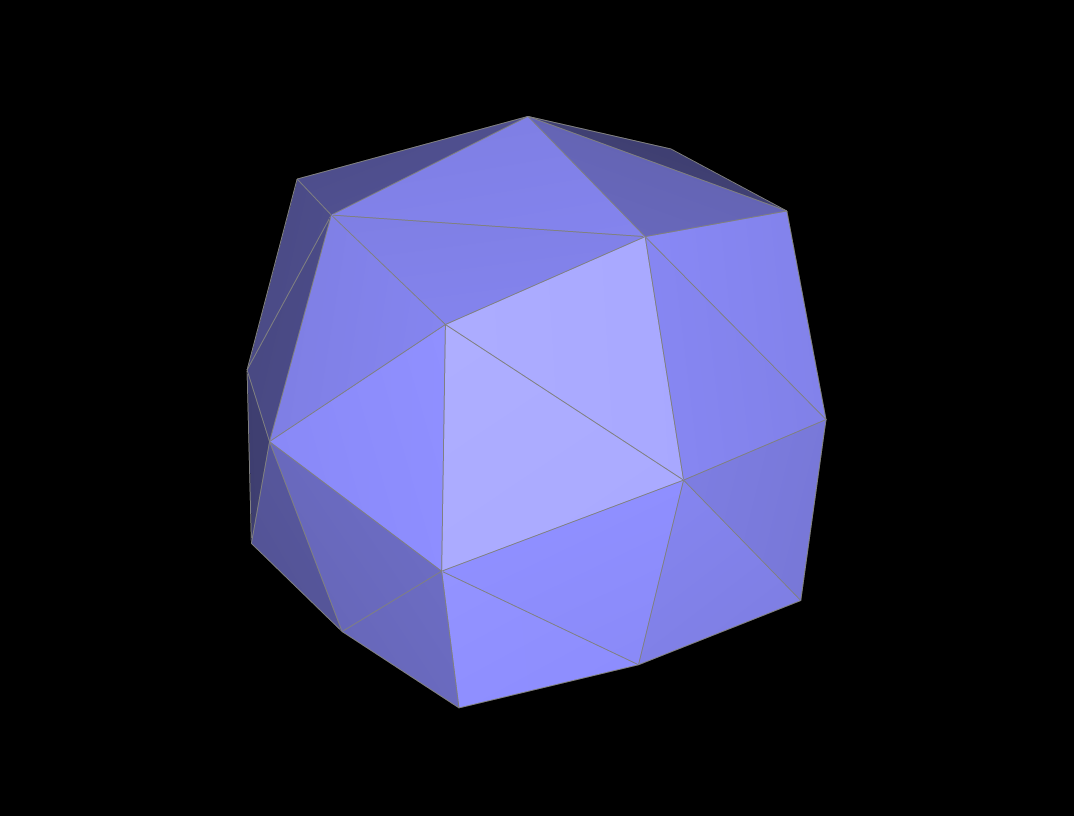
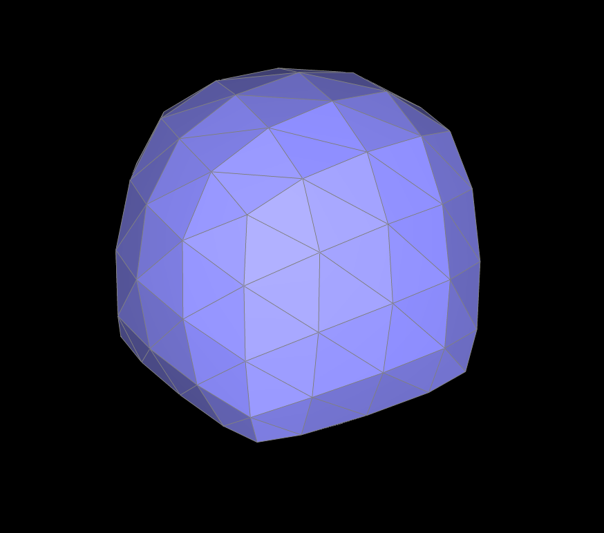
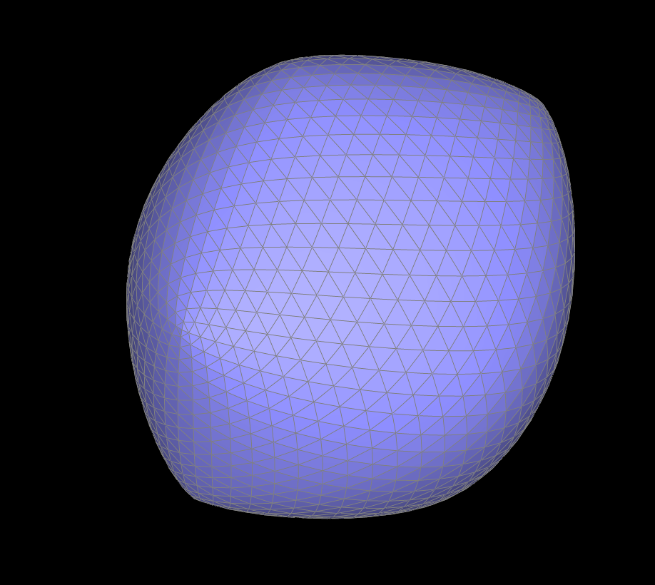
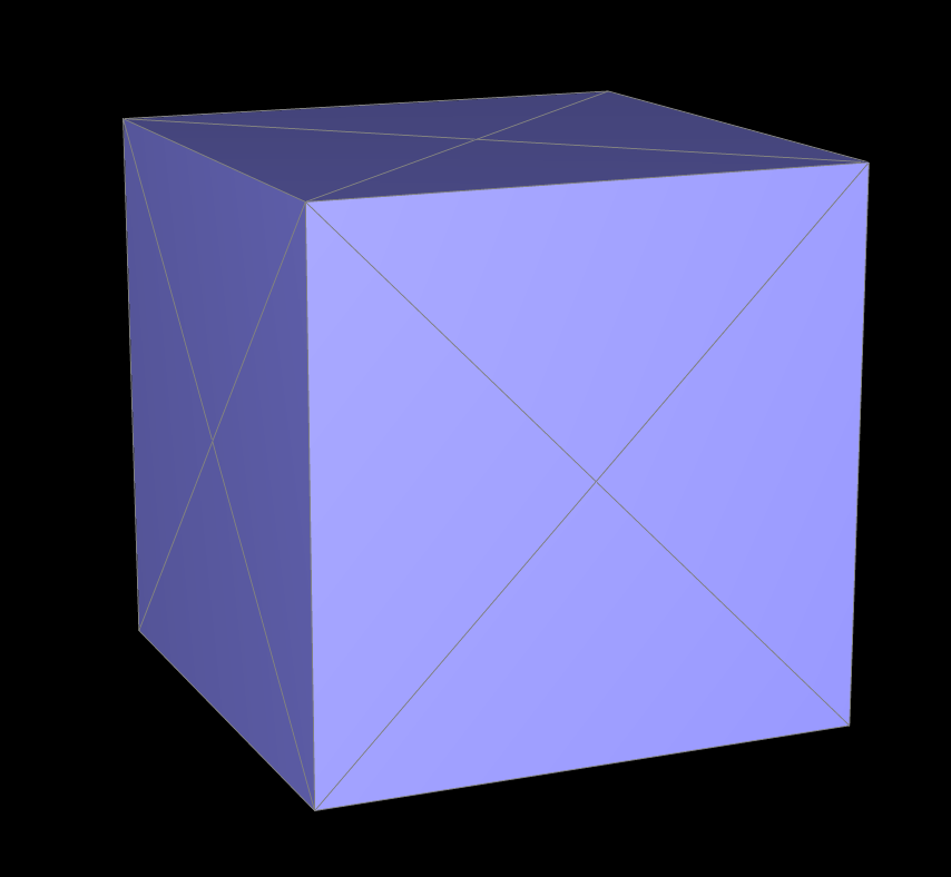
Take some notes, as well as some screenshots, of your observations on how meshes behave after loop subdivision. What happens to sharp corners and edges? Can you reduce this effect by pre-splitting some edges?
The sharp edges of the torus shape become smoothed out prior after multiple iterations of subdivision. In this case, the torus mesh was symmetric in its distribution of faces, so the final mesh after subidivision came out looking smooth and balanced.
|

|
|
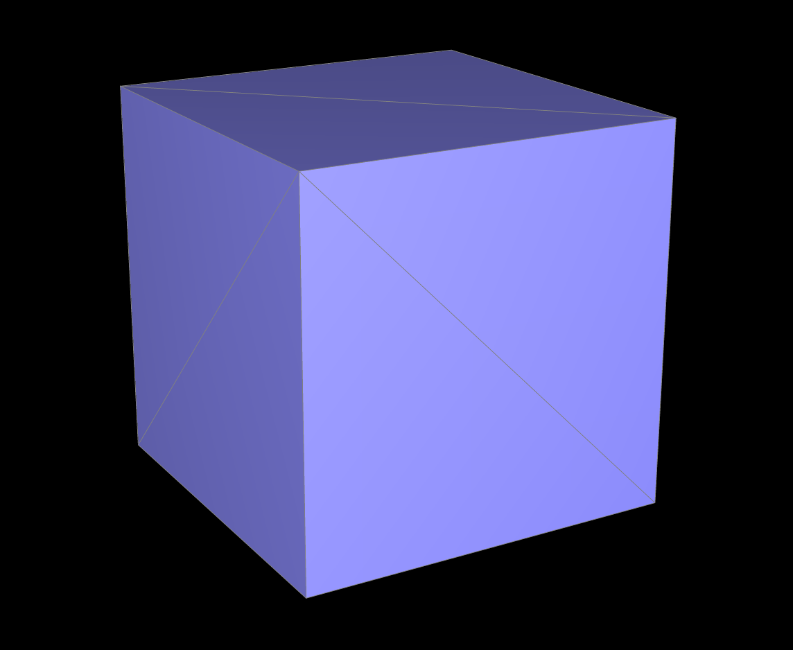
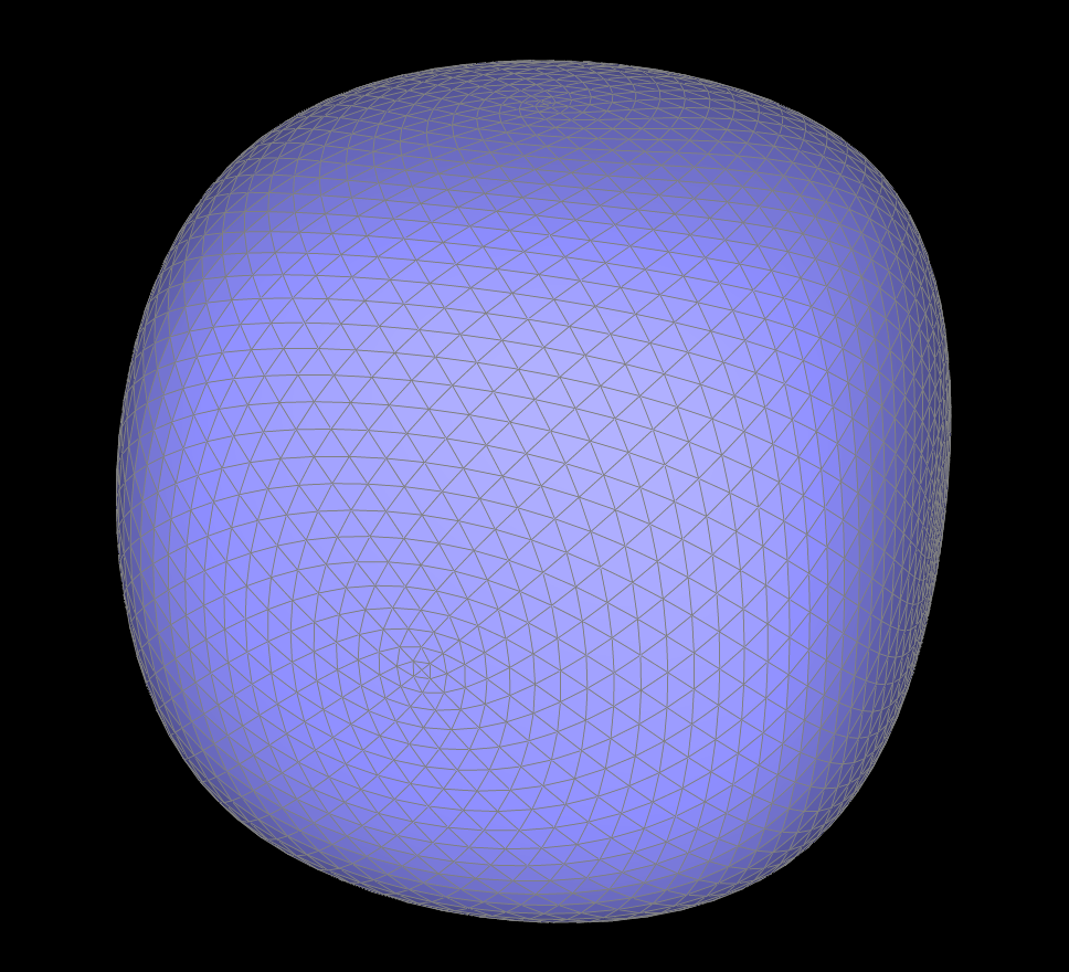
From the cube example, we saw that one level of loop subdivision immediately smoothed out all sharp corners and edges, and continually smoothed it even more after each subdivision. When we manually pre-split some edges to make it more balanced (i.e. the splits were the same on all faces of the cube), we noticed it outputted a more smoothed shape and the initial corners were less present. This is in contrast to not pre-splitting where the faces of the cube had complete opposites splits, which caused the output to be more blocky and coarse.
|
|
|
|
|
|
|
|
If you have implemented any extra credit extensions, explain what you did and document how they work with screenshots.
YOUR RESPONSE GOES HERE
Part 7 (Optional, Possible Extra Credit)
Save your best polygon mesh as partsevenmodel.dae in your docs folder and show us a screenshot of the mesh in your write-up.YOUR RESPONSE GOES HERE
Include a series of screenshots showing your original mesh and your mesh after one and two rounds of subdivision. If you have used custom shaders, include screenshots of your mesh with those shaders applied as well.
YOUR RESPONSE GOES HERE
Describe what you have done to enhance your mesh beyond the simple humanoid mesh described in the tutorial.
YOUR RESPONSE GOES HERE
THIS IS OUR WEBSITE: https://cal-cs184-student.github.io/sp23-project-webpages-horseshoe/proj2/index.html