Overview
In this project we implemented Castelja's algorithm, Bezier surfaces, area weighted normal vectors, and loop subdivision in order to smooth out rendered objects. In the end, it was really satisfying to be able to see the objects become smoother as they performed such operations on them. I learned that most objects can really just be represented by halfedges and that manipulating flips and splits can take you a long way.
Section I: Bezier Curves and Surfaces
Part 1: Bezier curves with 1D de Casteljau subdivision
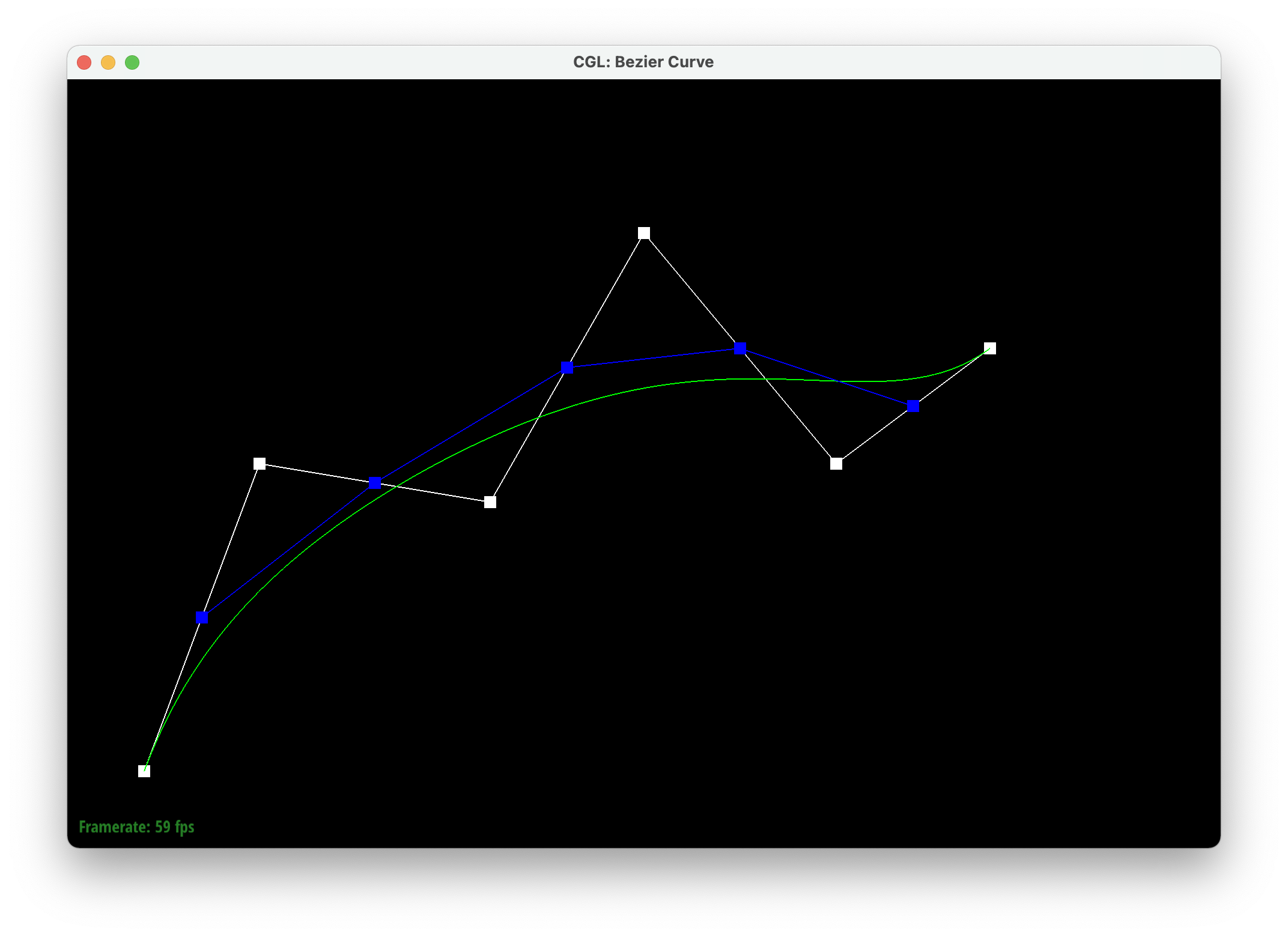
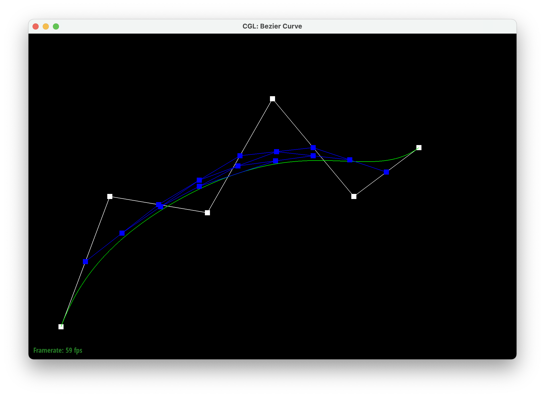
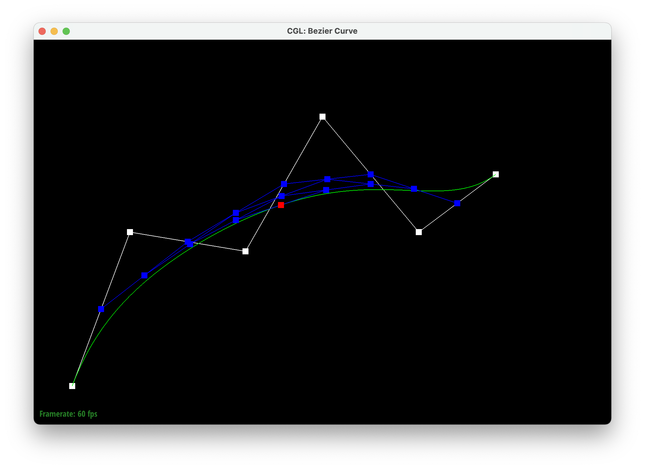
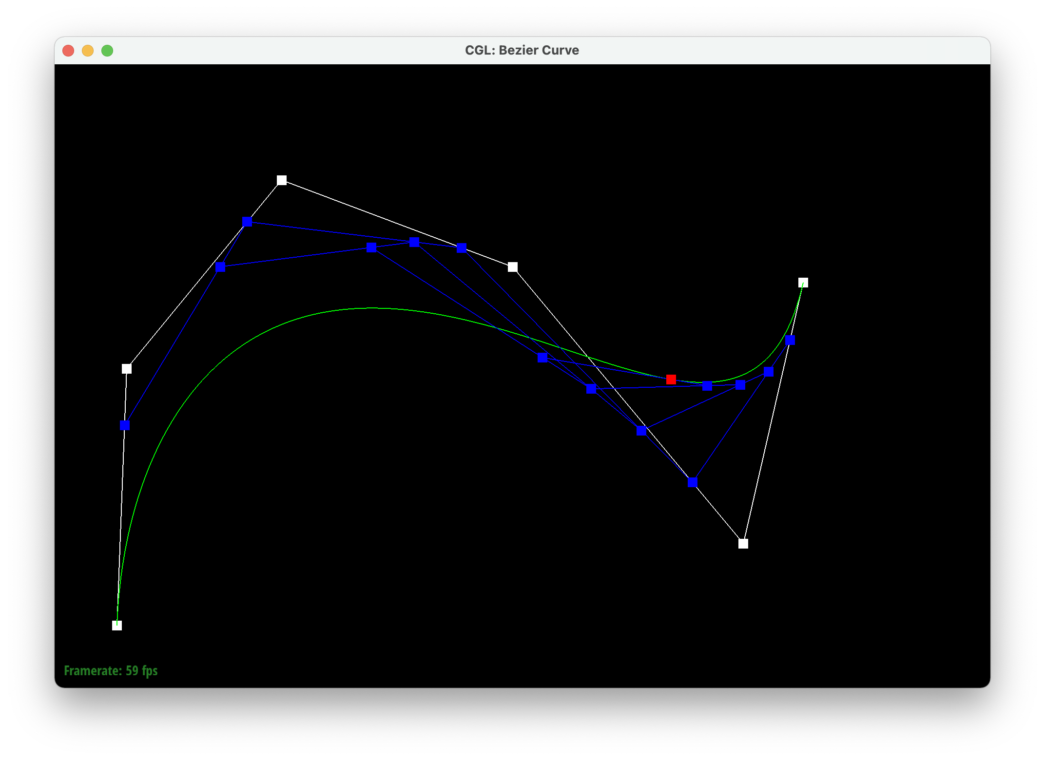
Casteljau's algorithm takes a line with at least three points and creates new points using linear interpolation (lerps) on each edge and does this recursively until we're left with one point in the middle. This final point falls on the bezier curve. We implemented this by first creating a temporary 2D vector, which is meant to store the previous point, and a 2D vector to return. We iterate through each control point and interpolate it with the previous point with parameter t, and store the resulting point in the 2D vector to return. We then return the vector used to store the interpolated points.
|

|

|
|
|
|
Part 2: Bezier surfaces with separable 1D de Casteljau subdivision
Casteljau's algorithm extends to Bezier surfaces because we extend it to a 3D space by adding variable z and using a n x n grid of control points. First, we implement evaluateStep, which is Casteljau's algorithm but with the addition of a z coordinate. Next, we implement evaluate1D, which repeatedly calls evaluateStep with parameter t on a given vector of points until one point is left. Lastly, we implement evaluate, which calls evaluate1D with parameter u on every row within the nxn grid of control points. It stores the resulting points in a vector and then calls evaulate1D with parameter v on the resulting vector to get our final interpolated vector.
Section II: Sampling
Part 3: Average normals for half-edge meshes
We implemented this by iterating through all of the neighboring halfedges and adding the normal of each neighboring face (the cross product of the current neighboring vertex position minus the original vertex position and the next neighboring vertex position minus the original vertex position) to a summation vector. After iterating through all of the neighboring halfedges, we return the normalized vector of the summation of all the cross products.

|
|
Part 4: Half-edge flip
We implemented edge flips by first having a check to see if the edge was a boundary, which meant that it couldn't be flipped and we returned an empty EdgeIter. We then grabbed all of the edges, halfedges, vertices, and faces to be able to know what is supposed to be flipped. Using a picture of a triangle with everything named, we then reassigned everything to ensure that every halfedge, edge, vertex, and face had the correct components. We debugged by checking to see if the right part was assigned to the right spot in the GUI. Later on in part 6, we caught a bug in part 4 where we assigned the outside halfedges to the wrong faces and it created a hole in the mesh later on.
|
|
Part 5: Half-edge split
We implemented edge splits by first having a check to see if the edge was a boundary, which meant that it couldn't be flipped and we returned an empty EdgeIter. We then grabbed all of the halfedges, vertexes, edges and faces to be able to reassign them later. We then created new halfedges, faces, edges, and a vertex to account for the split. Using all this information that we have, we used a diagram to assign the right parts after the split and made sure to give the newly created components the right assignments that each needed. We also set up a newPosition to use in part 6 and isNew on the newly created components. Our split edge worked alone but when we were debugging we saw that faces disappeared when we flipped and split. We had to go through our code to ensure everything was assigned correctly. We then figured out that our flip edge was assigning the wrong faces which created the holes in the mesh
|
|
|
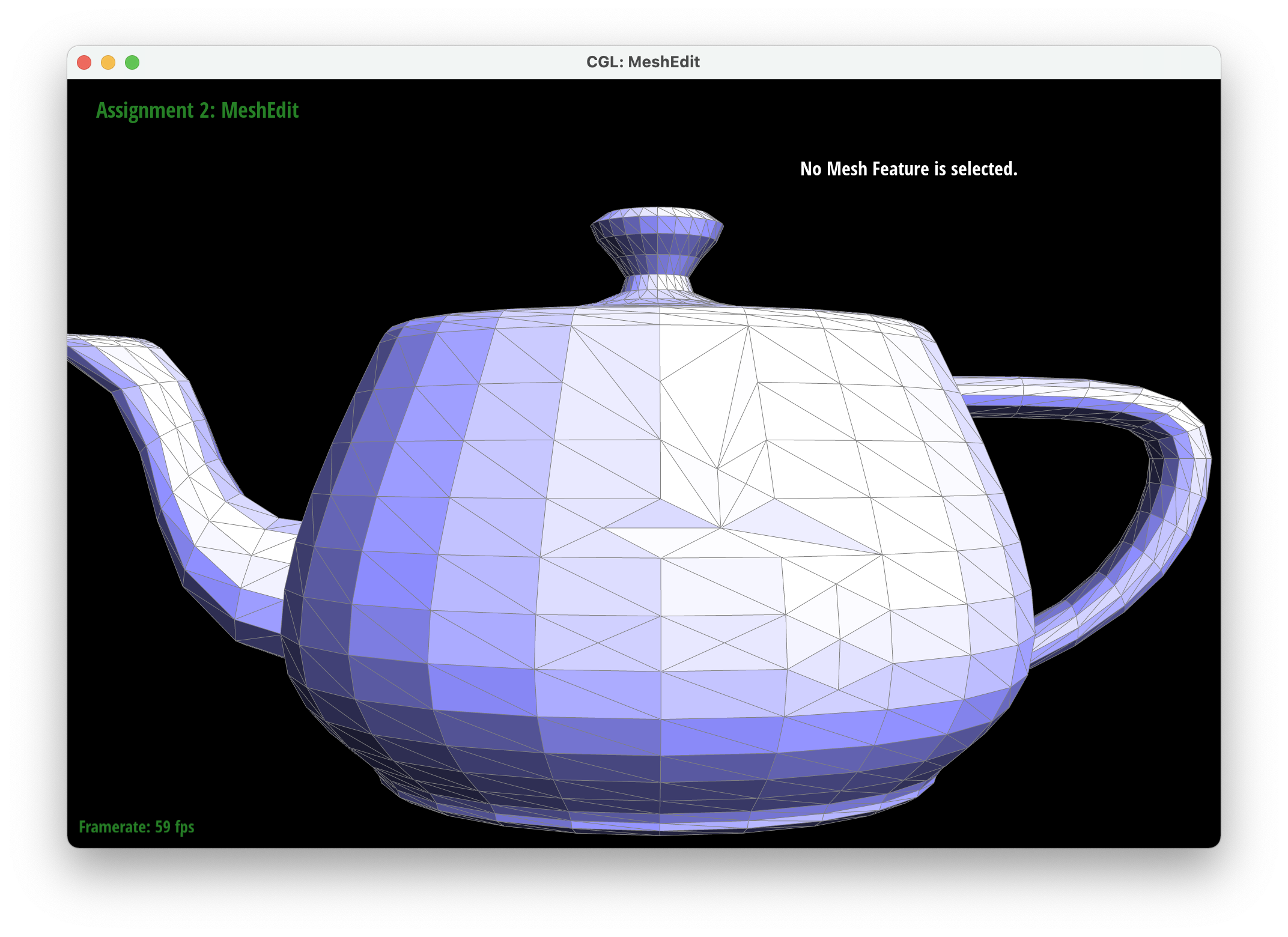
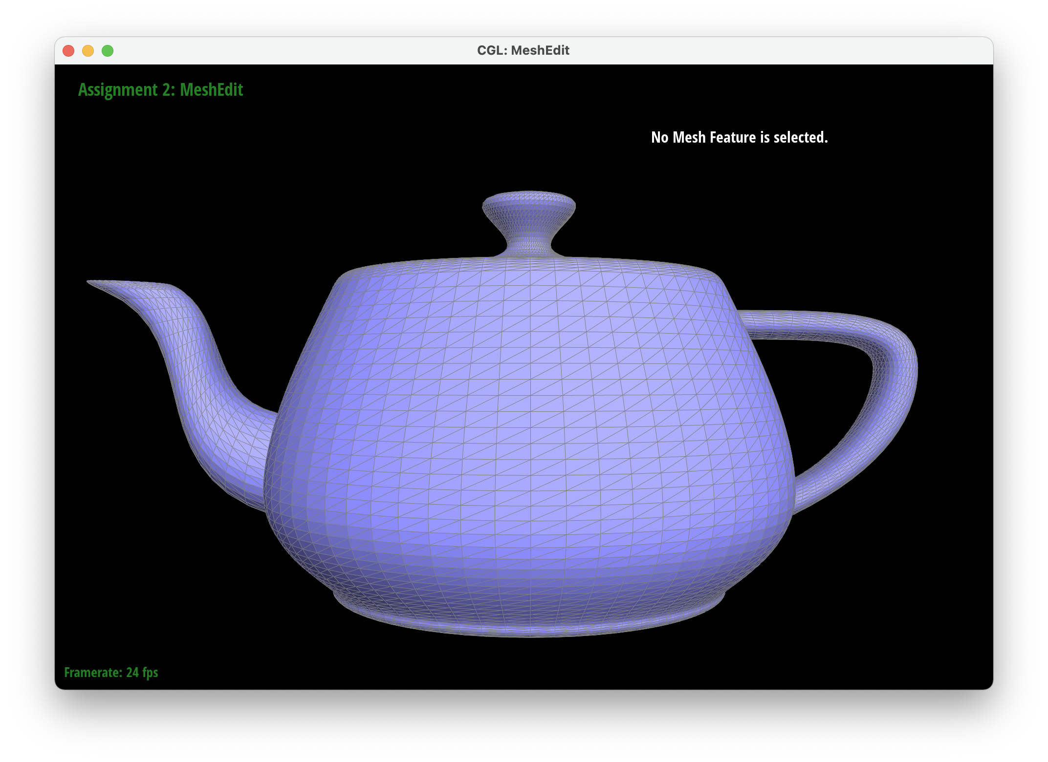
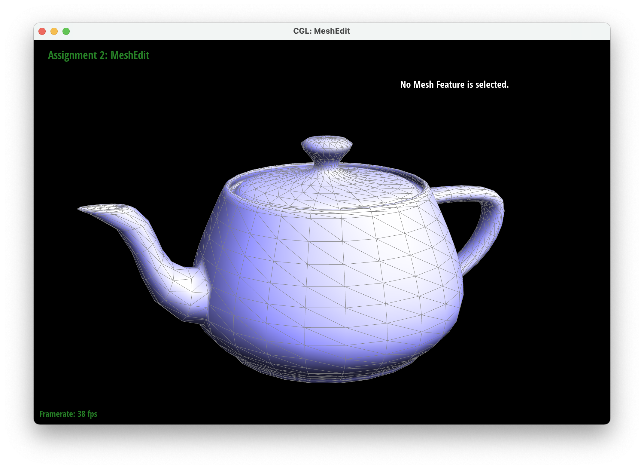
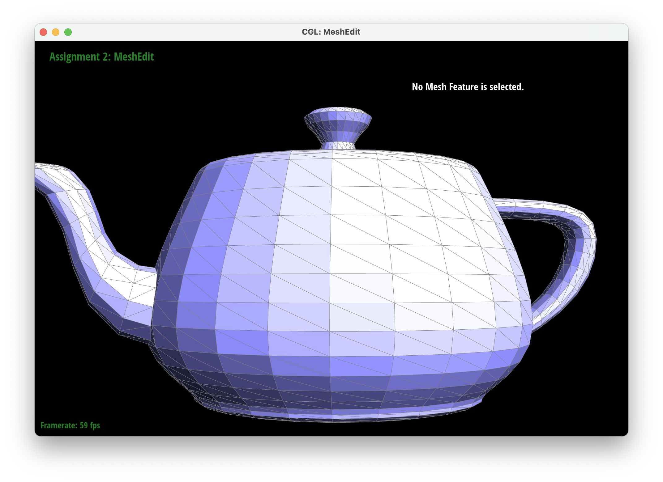
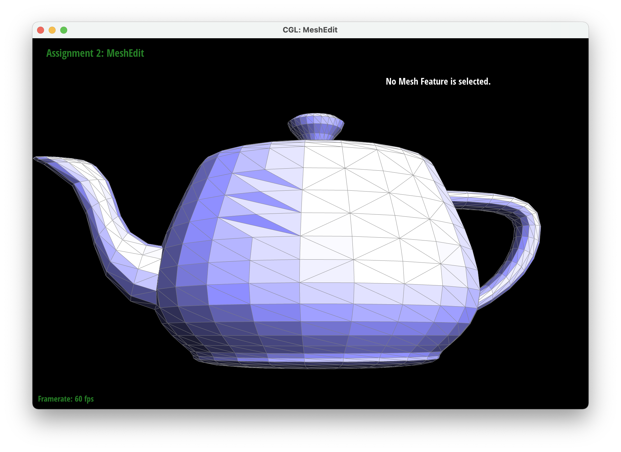
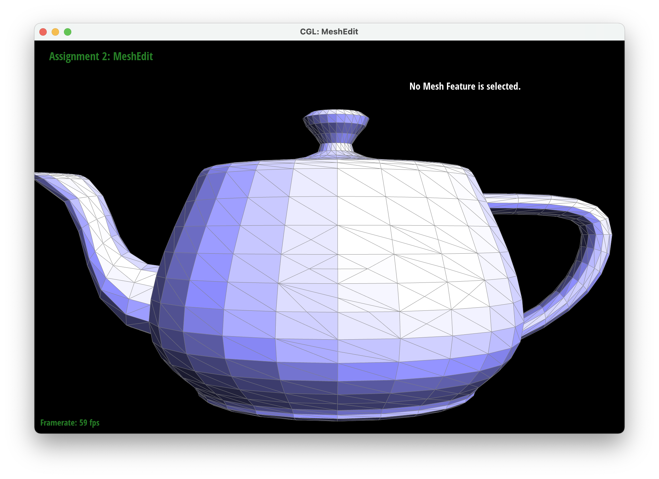
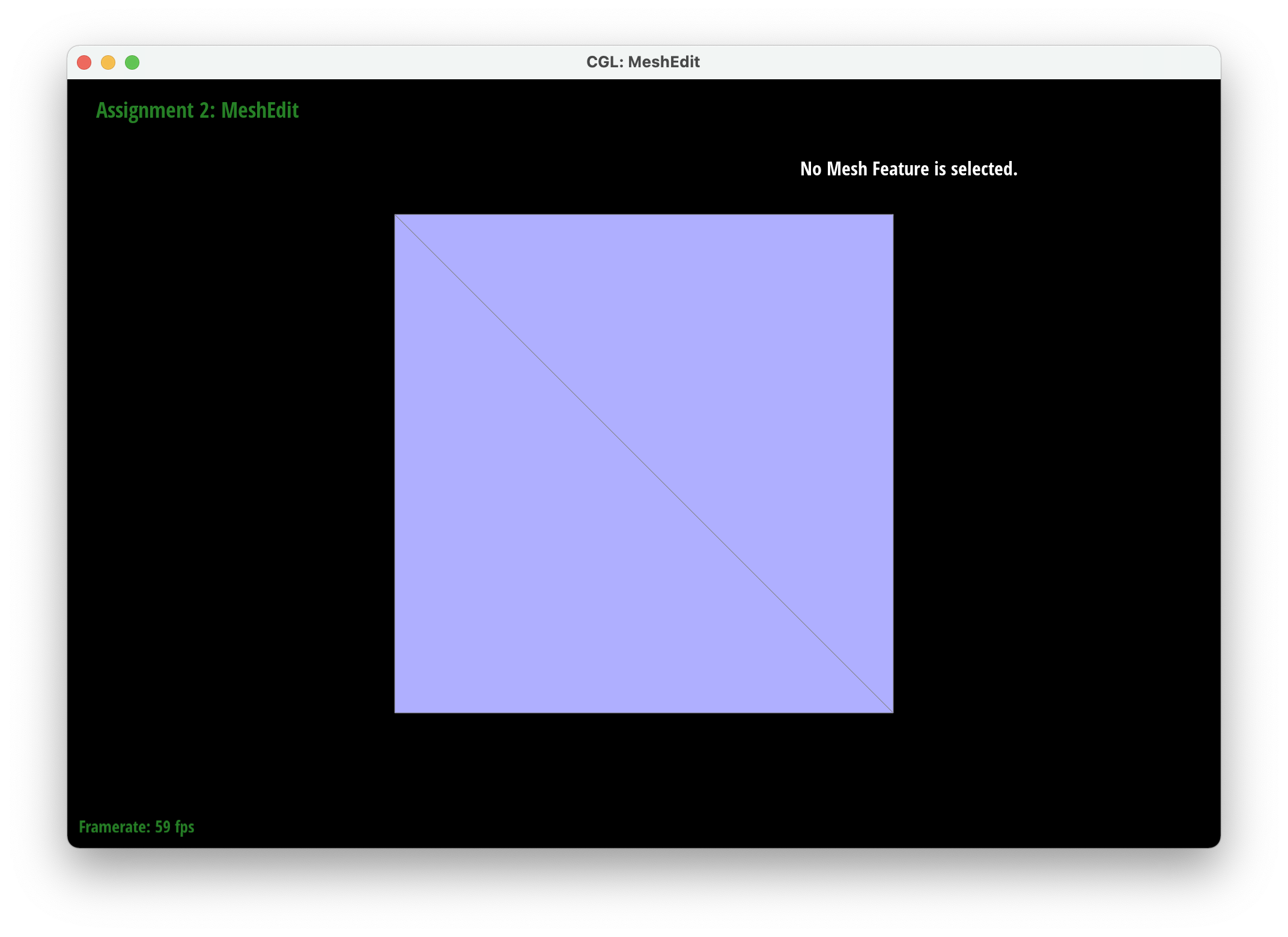
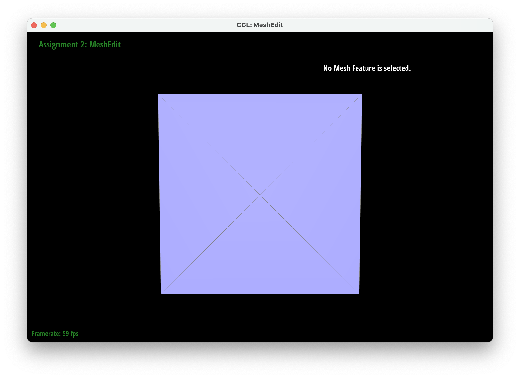
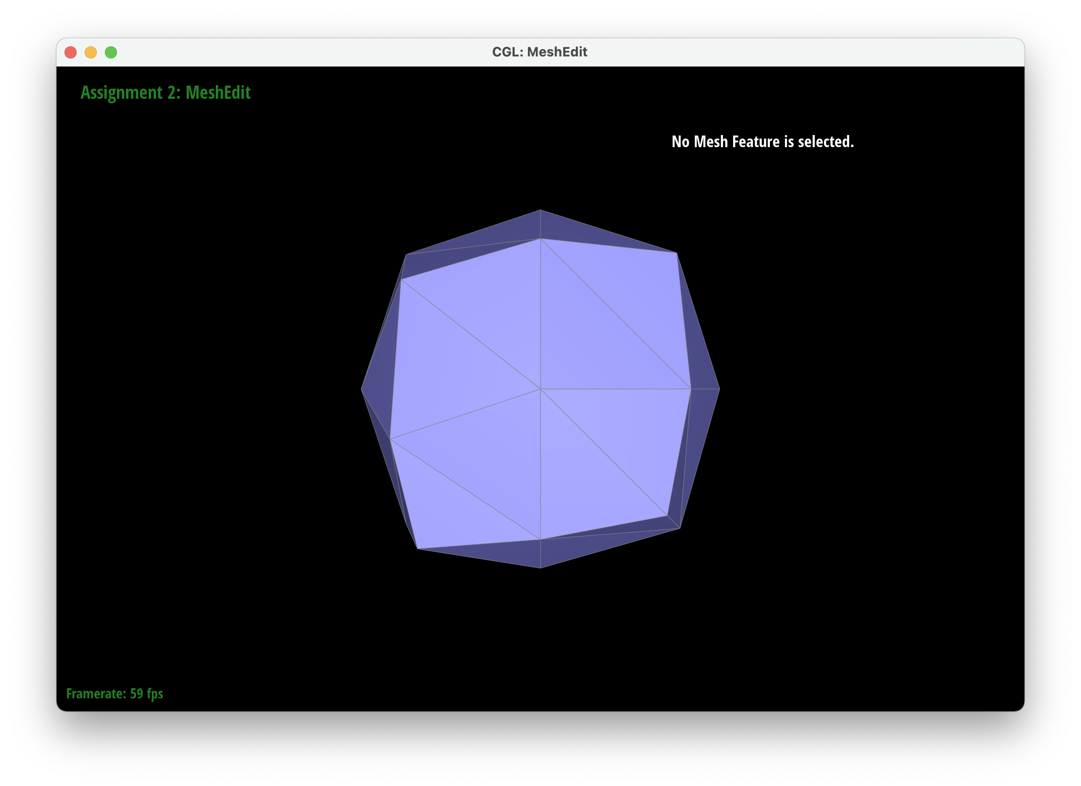
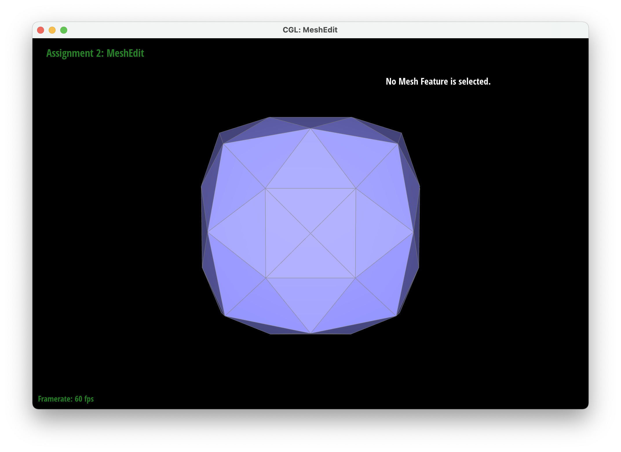
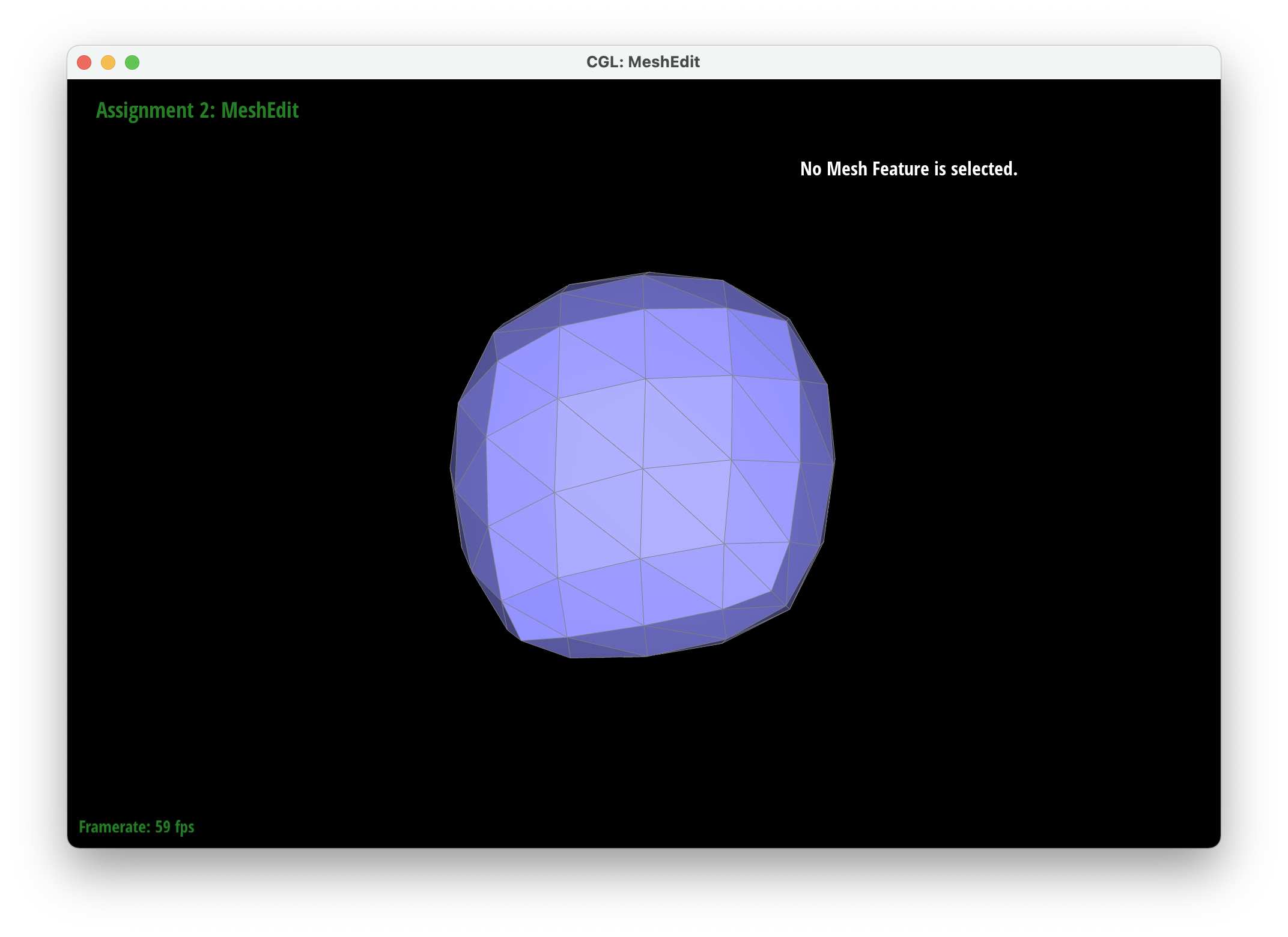
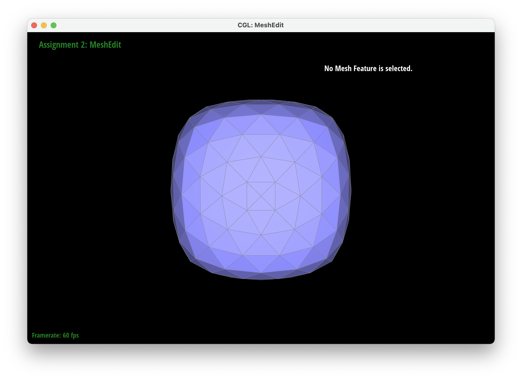
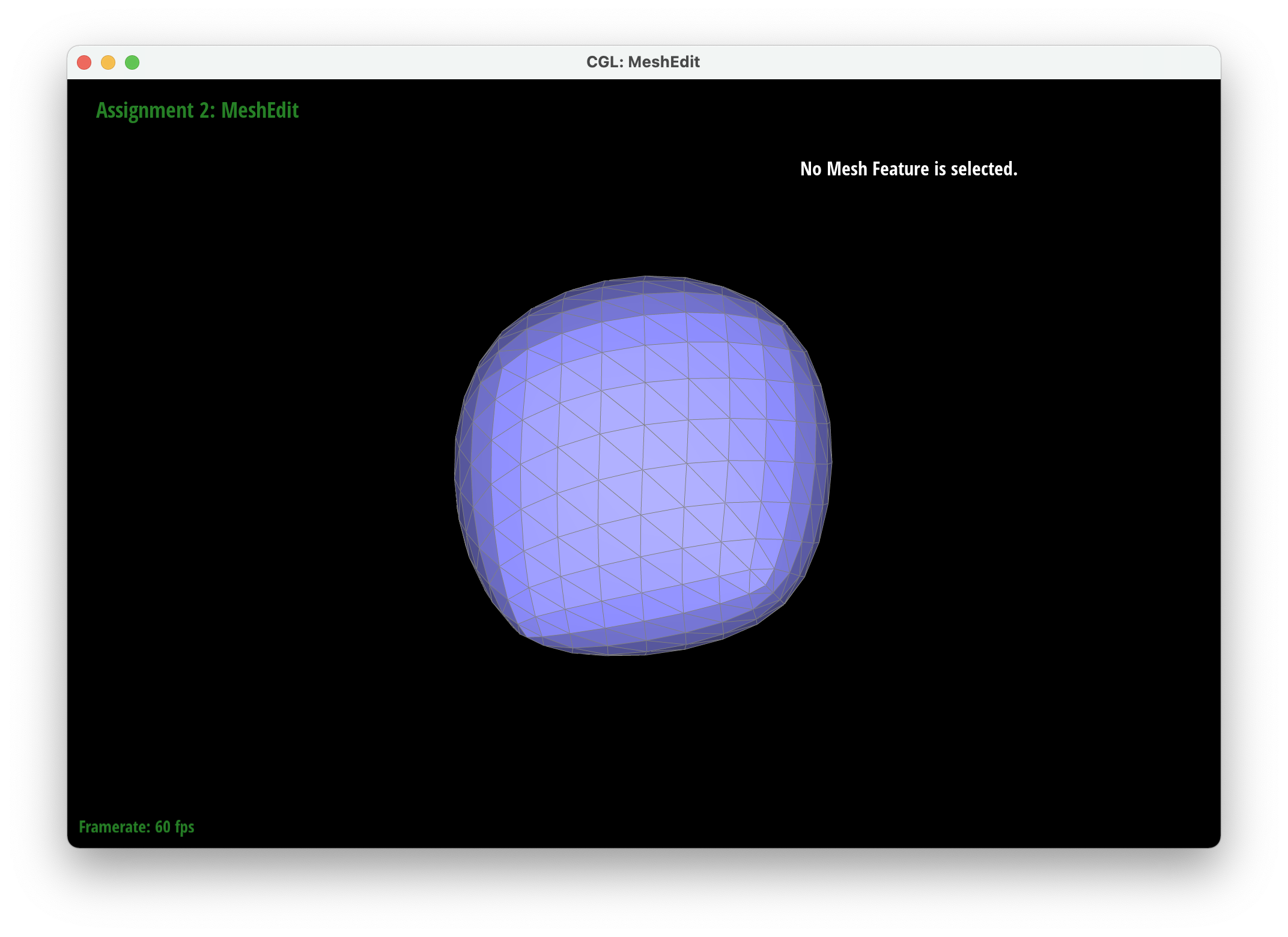
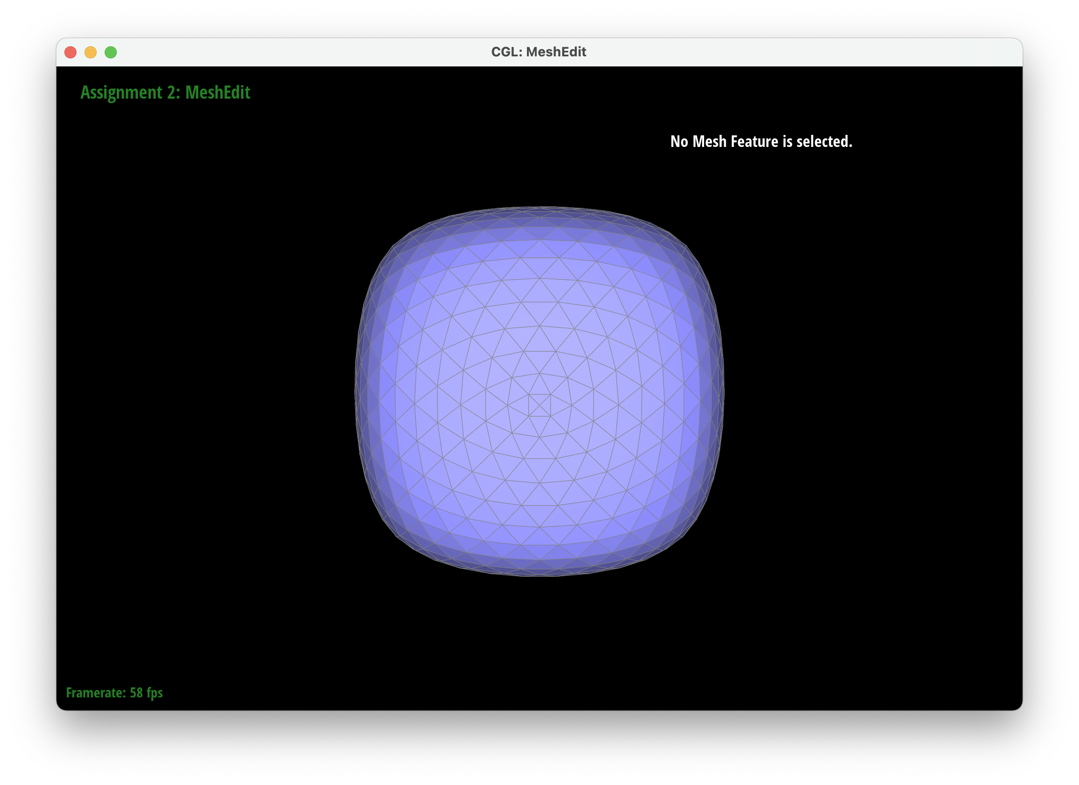
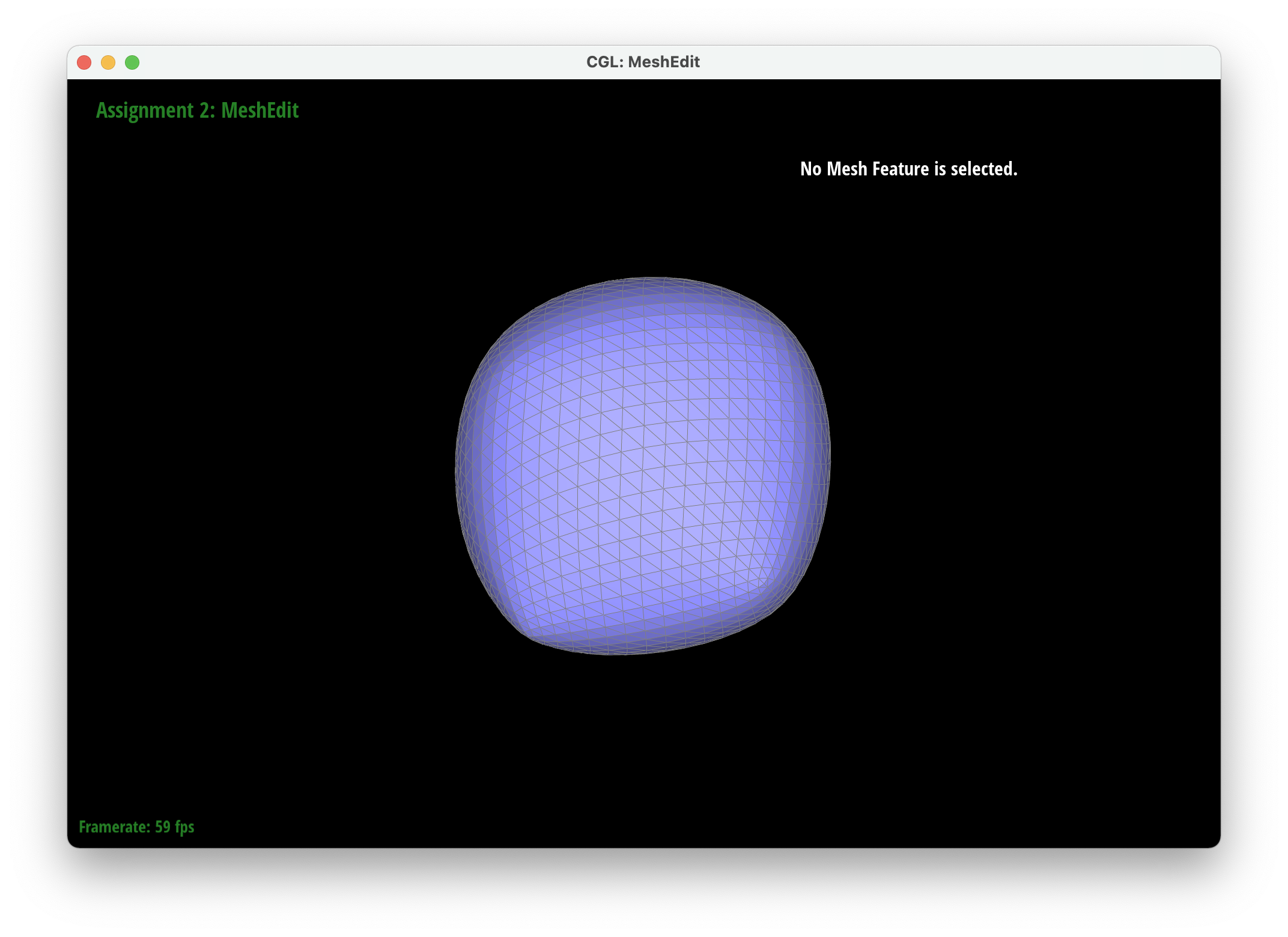
Part 6: Loop subdivision for mesh upsampling
We implemented upsampling by first going through all of the vertices and edges and marking their isNew attribute to false. This ensured that we started a mesh that had no new components. We then iterated through all of the edges in the mesh and set the new positions attribute of each edge to be the new vertices created after the edge is split. Then we iterated through all the vertices in the mesh and set their new position attributes according to their degree and the positions of their neighboring vertices. . We then went through our edges and split them only if their vertices were old to ensure we only split old edges. After splitting, we iterated through every edge again and flipped edges only if they were connected to a new vertex and an old vertex and if the edge was new (we also modified edgeSplit so that the isNew attributes of new vertices and edges are set to true). Finally, we set all the vertex positions to the position stored in the new position attirbute. To debug, we would isolate different parts of our upsampling code to make sure each part was working correctly so we could tackle smaller problems rather than tackling all the issues at once. For example, we were able to determine that our previous method for finding the new positions of the new vertices was incorrect by only updating the positions of the new vertices and then realizing that it made our output asymmetrical.
After loop division, meshes lose their sharp edges and corners gradually. The blockiness is lost especially in the cube we used which takes on a rounder shape the more you subdivide it. Pre-splitting does help to get a sharper image. Since there are more edges to split, the shape stays more similar by losing less of its structure as you subdivide it. Adding some splits and flips to the cube so that the edges of each face is symmetrical helps make the mesh stay symmetrical as you upsample.
|
|
|
|
|
|
|
|
|

|
Section III: Optional Extra Credit
If you are not participating in the optional mesh competition, don't worry about this section!