CS184/284A Spring 2025 Homework 2 Write-Up
Link to webpage: cal-cs184-student.github.io/hw-webpages-zaddle55/hw2
Link to GitHub repository: github.com/cal-cs184-student/hw-webpages-zaddle55
Overview
In this homework, we deep dive into the world of geometric modeling, constructing the procedure of rendering a Bezier surface and implementing the half-edge mesh upsampling algorithm. These alogorithm are extremely fundamental and efficient tools in the field of computer graphics. Also it's amazing to see the teapot rendered in the end! We also have an optional extra credit section for you to get creative and model something fun, so be sure to check that out as well.Section I: Bezier Curves and Surfaces
Part 1: Bezier curves with 1D de Casteljau subdivision
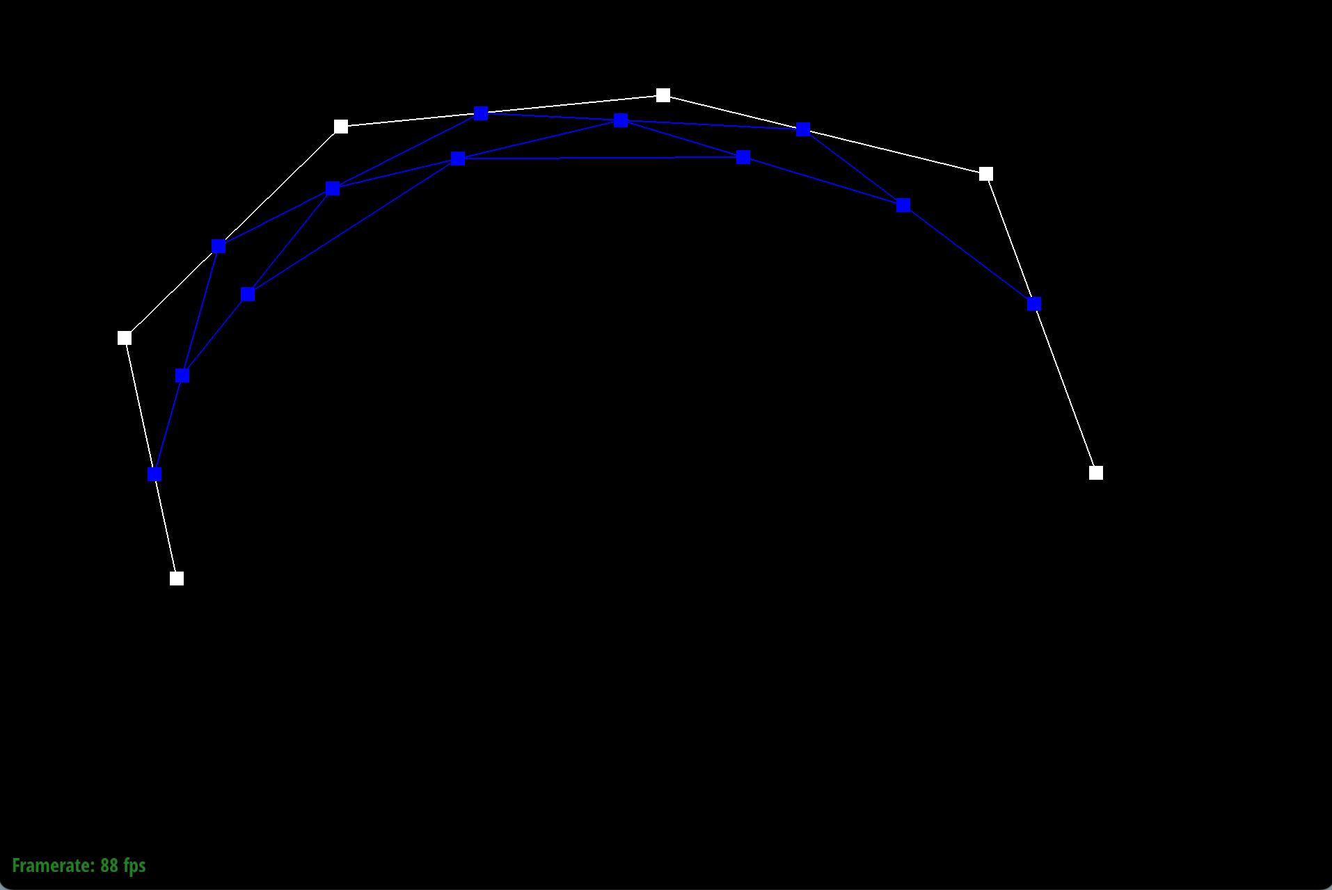
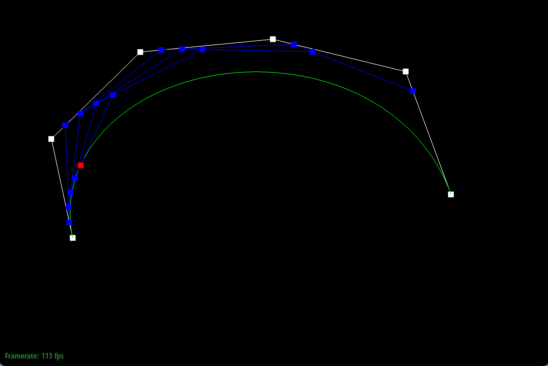
This graph describes the 1D de Casteljau subdivision step for a cubic Bezier curve.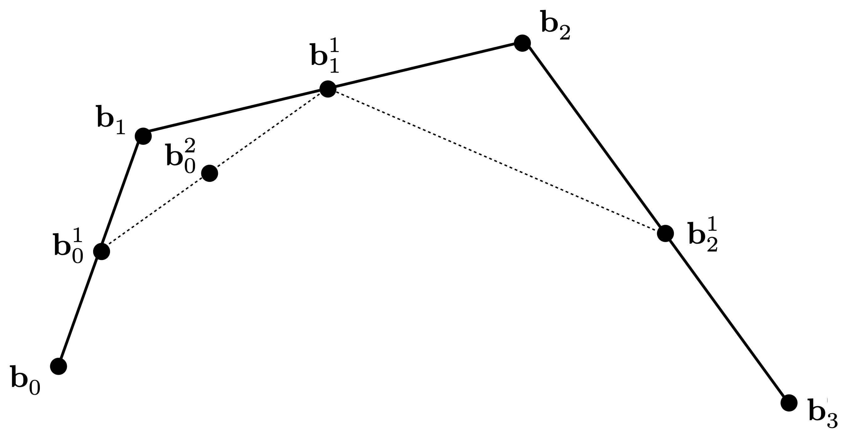 For \(n\) control points, we need to perform \(n-1\) lerp operations and get \(n-1\) intermediate points.
We can do this by set up an array of size \(n-1\) to store the intermediate points, and iteratively update the array with the new intermediate points until we get down to 1 point, which is the point on the curve at parameter \(t\).
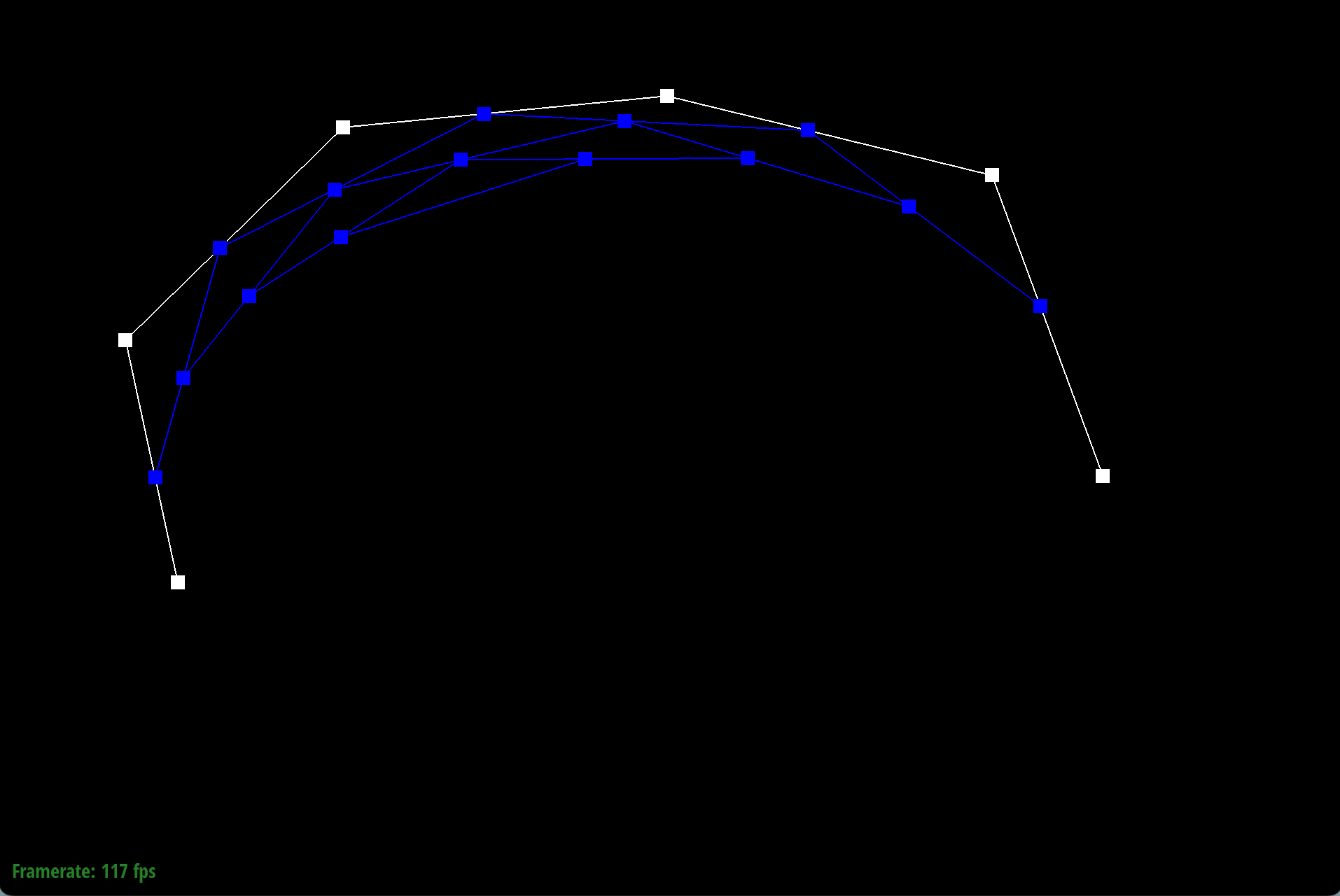
For \(n\) control points, we need to perform \(n-1\) lerp operations and get \(n-1\) intermediate points.
We can do this by set up an array of size \(n-1\) to store the intermediate points, and iteratively update the array with the new intermediate points until we get down to 1 point, which is the point on the curve at parameter \(t\).
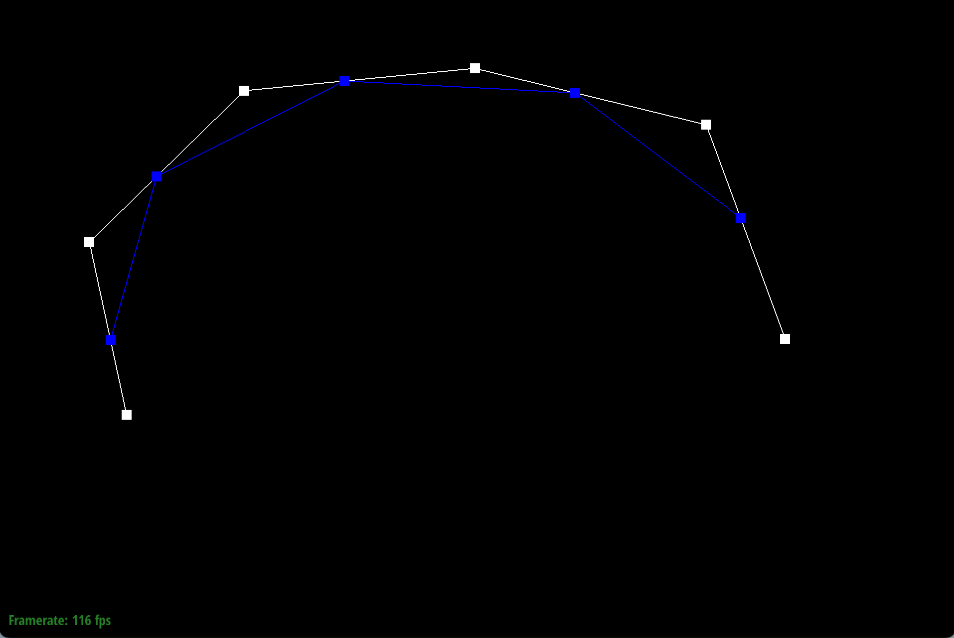
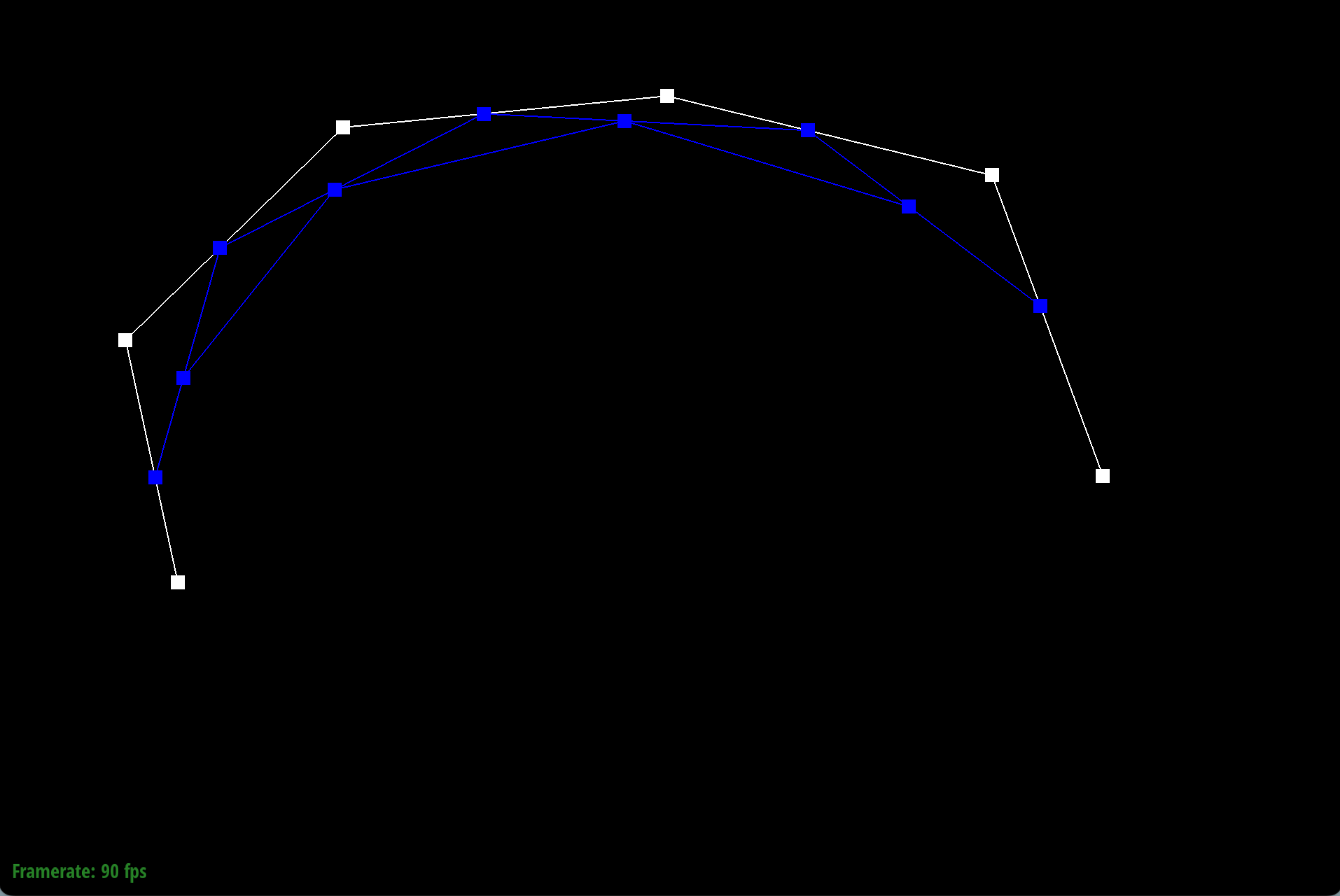
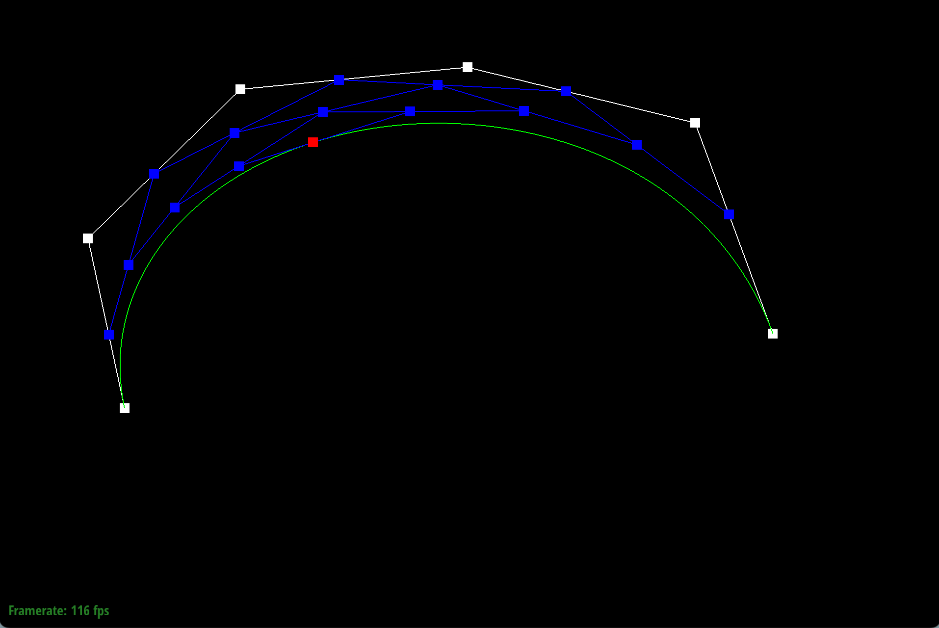
This is a simple example of how the de Casteljau subdivision works for a cubic Bezier curve of 6 control points.
|
|
|
|
|
|
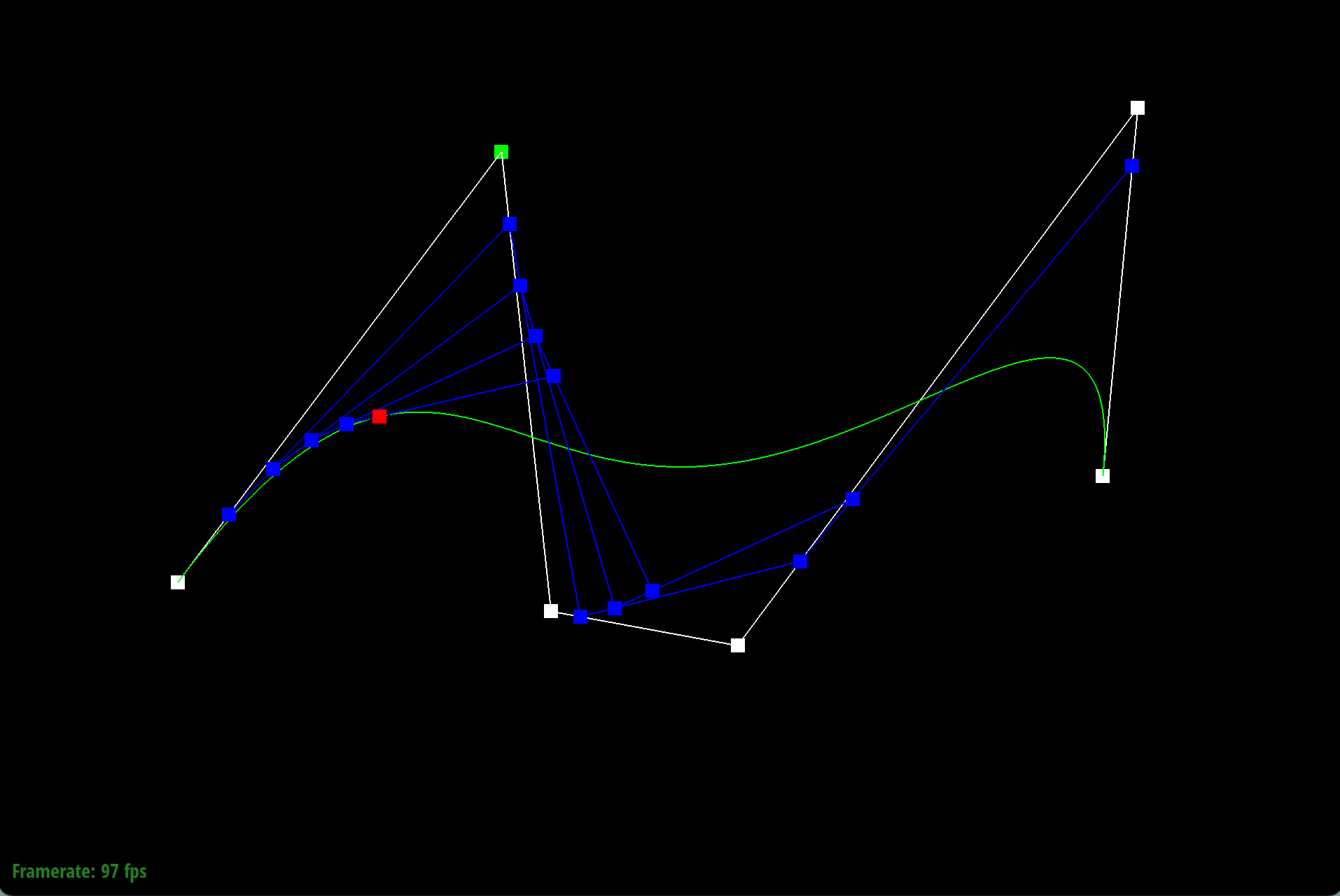
As we move the origin control point, the curve changes shape accordingly.
|
|
|
When we scroll the mouse to change parameter \(t\), the curve does not change shape. The final evaluate point moves along the curve as \(t\) changes.
|
|
|
Part 2: Bezier surfaces with separable 1D de Casteljau
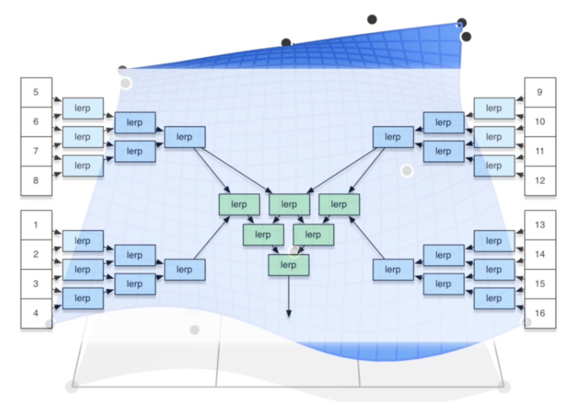
To move towards 2D Bezier surfaces, we can apply the 1D de Casteljau subdivision twice, first in one direction and then in the other direction. This is because the Bezier surface is defined as a tensor product of two sets of control points, one for each direction.First, the method BezierPatch::evaluateStep keep the same as the 1D version, so the code doesn't need to be modified.
Next, we will apply the 1D de Casteljau step for \(n-1\) times in one axis, recursion is used to implement the related function BezierPatch::evaluate1D.
Finally, we will apply the 1D de Casteljau step on the intermediate control points for \(m-1\) times in the other axis, using another parameter \(v\).
This graph describes the 2D de Casteljau subdivision step for a cubic Bezier surface.
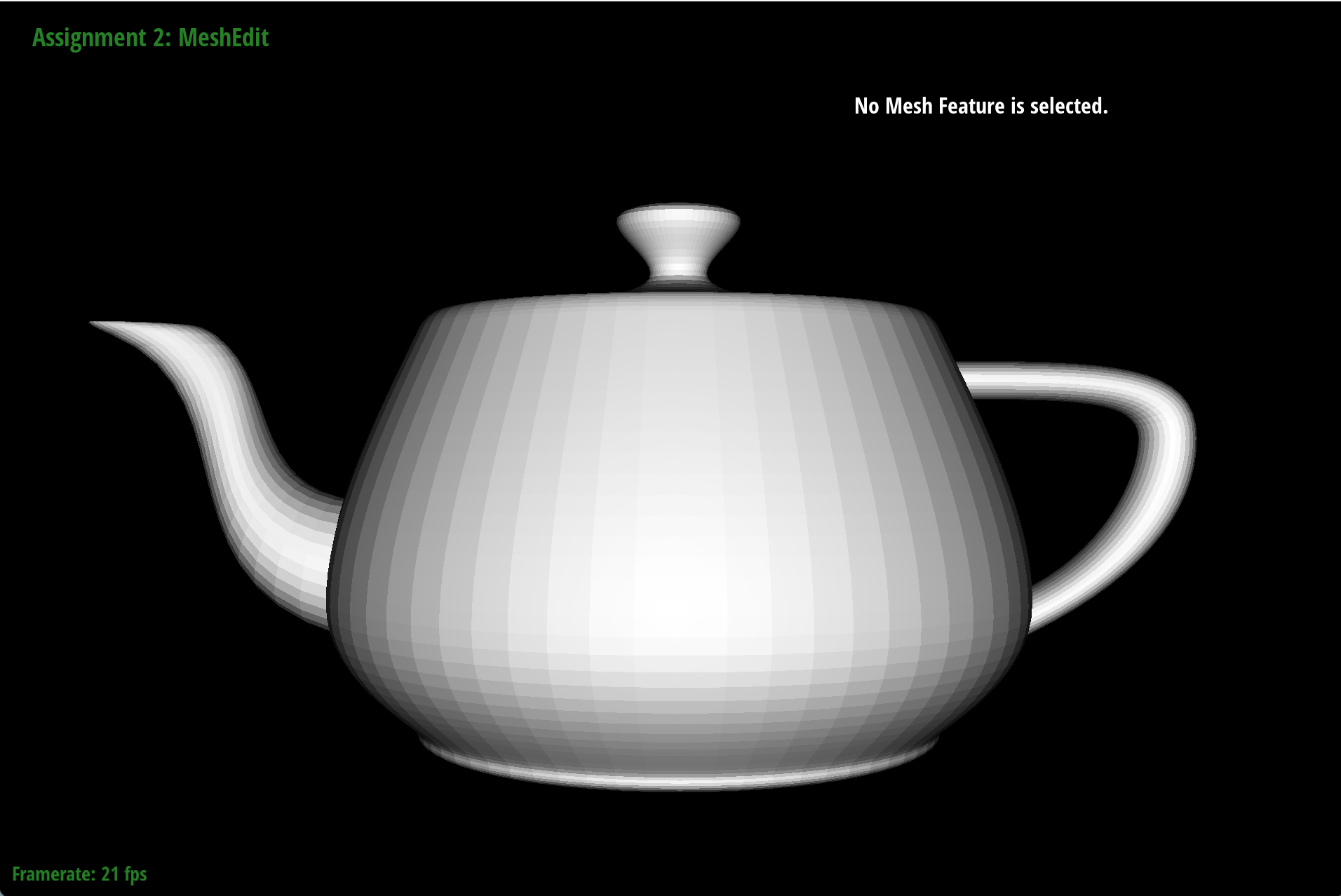
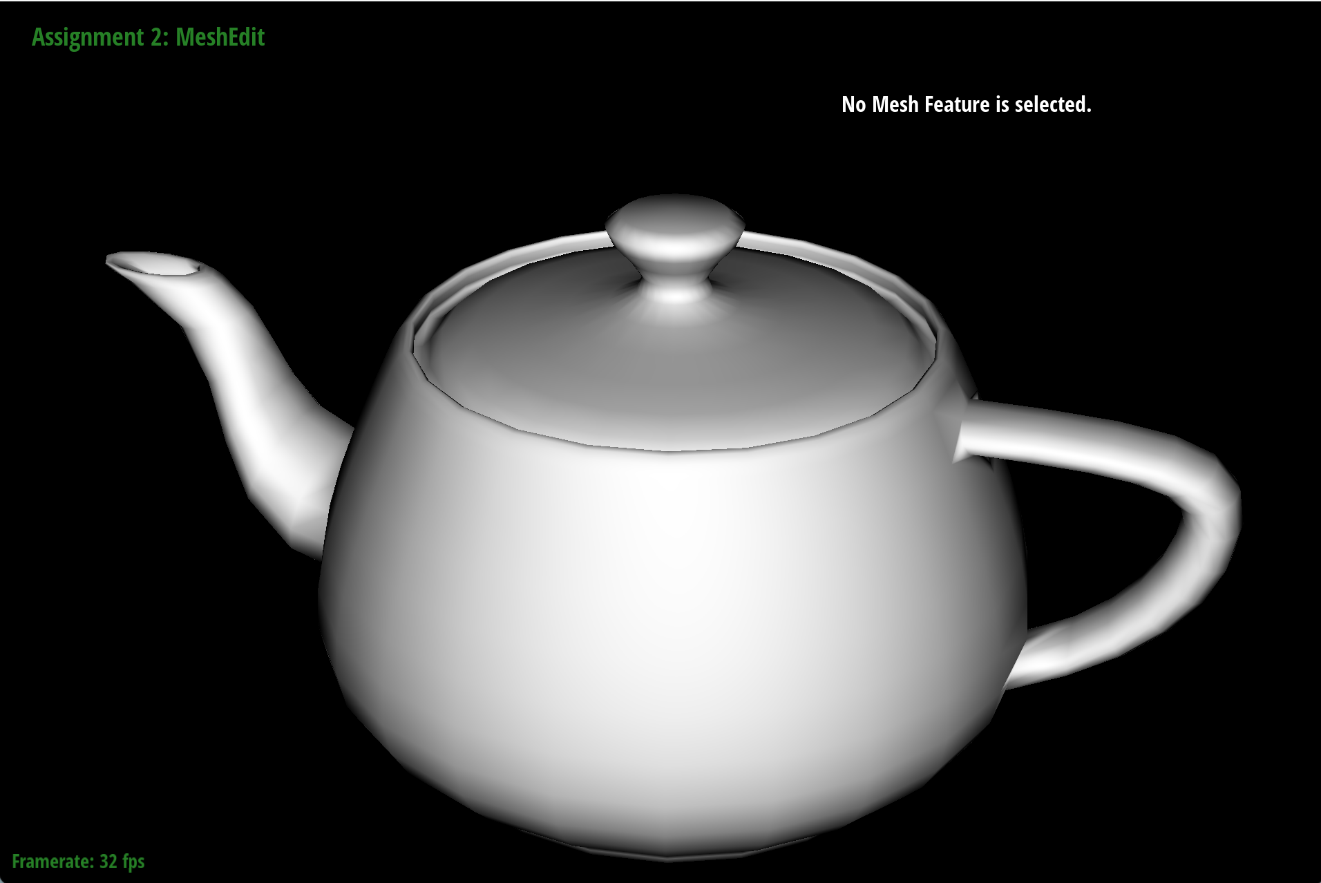
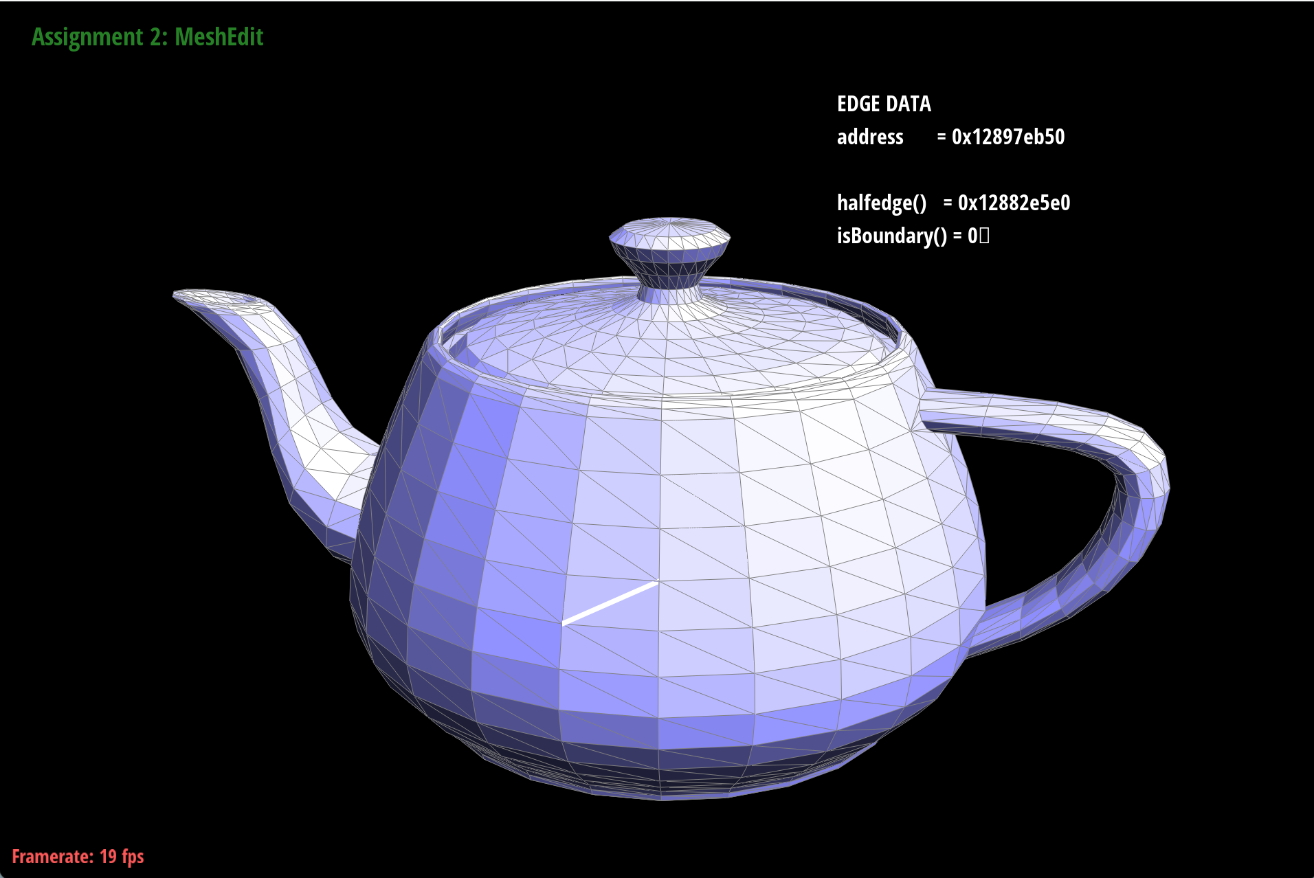
And this is the teapot rendered with the Bezier surface implementation!
Section II: Triangle Meshes and Half-Edge Data Structure
Part 3: Area-weighted vertex normals
To compute the area-weighted vertex normals, we can follow a manner similar to tranversing the neigboring halfedges of a vertex. We iteratively compute the normal of each neighboring face, which is given by the cross product of two edges of the face, and then we add up the normals of all neighboring faces to get the area-weighted vertex normal.Finally, we normalize the resulting normal vector to get the final vertex normal.
Here is an example of the effect of area-weighted vertex normals:

|
|
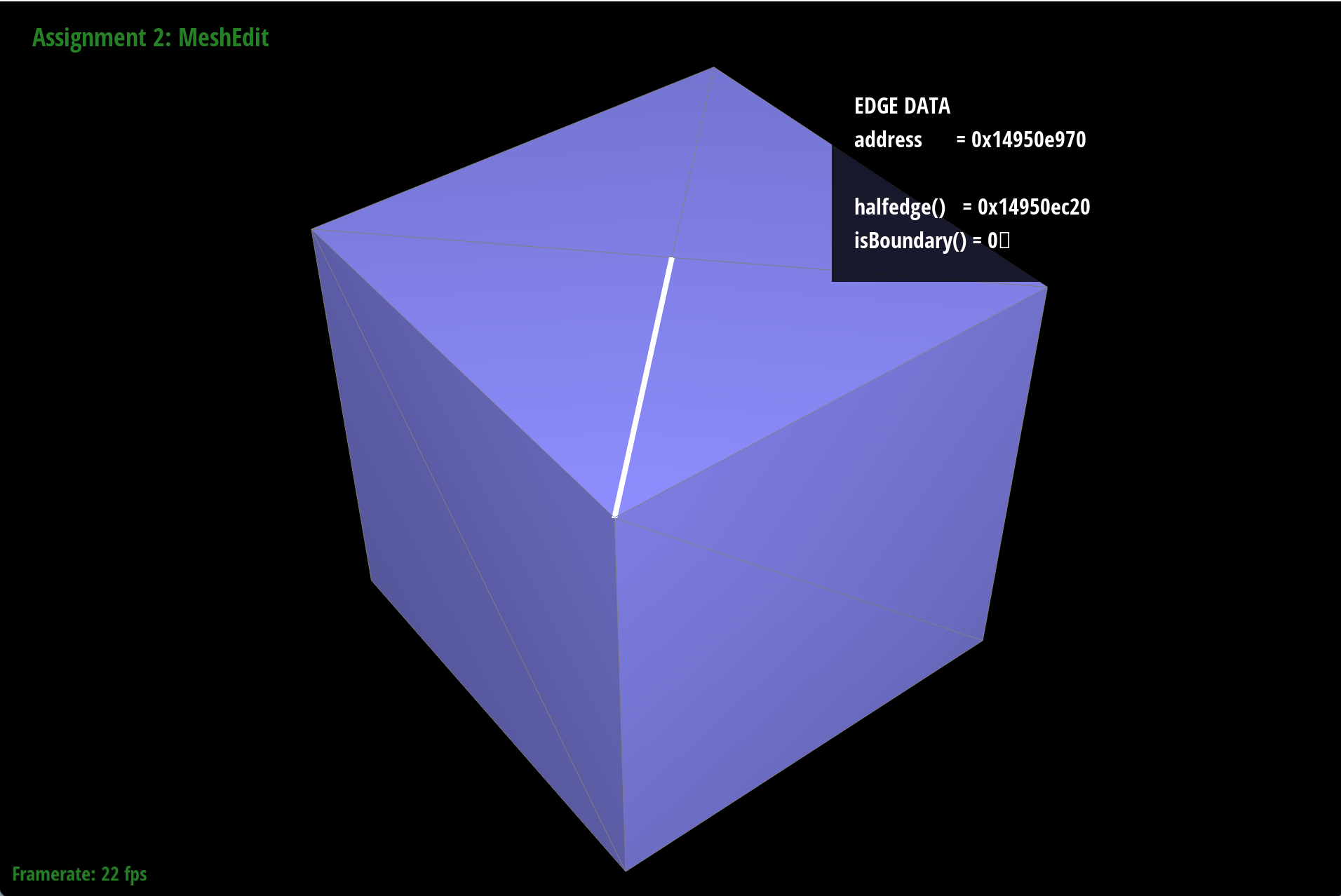
Part 4: Edge flip
To perform an edge flip, we first need to identify the two faces that share the edge we want to flip, and the four vertices that are involved in the edge flip operation. Then we will update the half-edge data structure by reassigning the half-edges and their corresponding vertices and faces according to the new configuration after the edge flip.This is an example of the effect of edge flip:

|
|
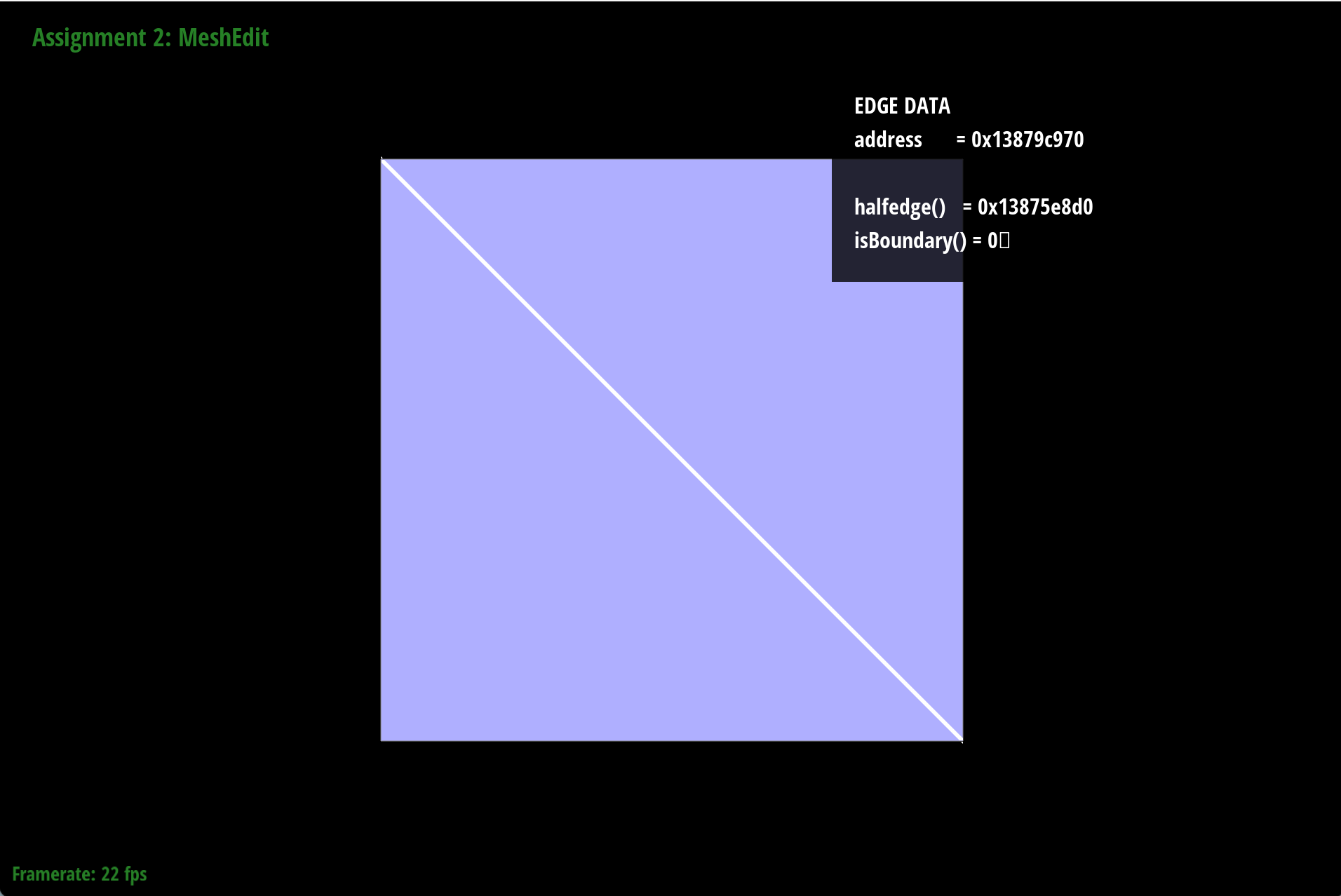
Part 5: Edge split
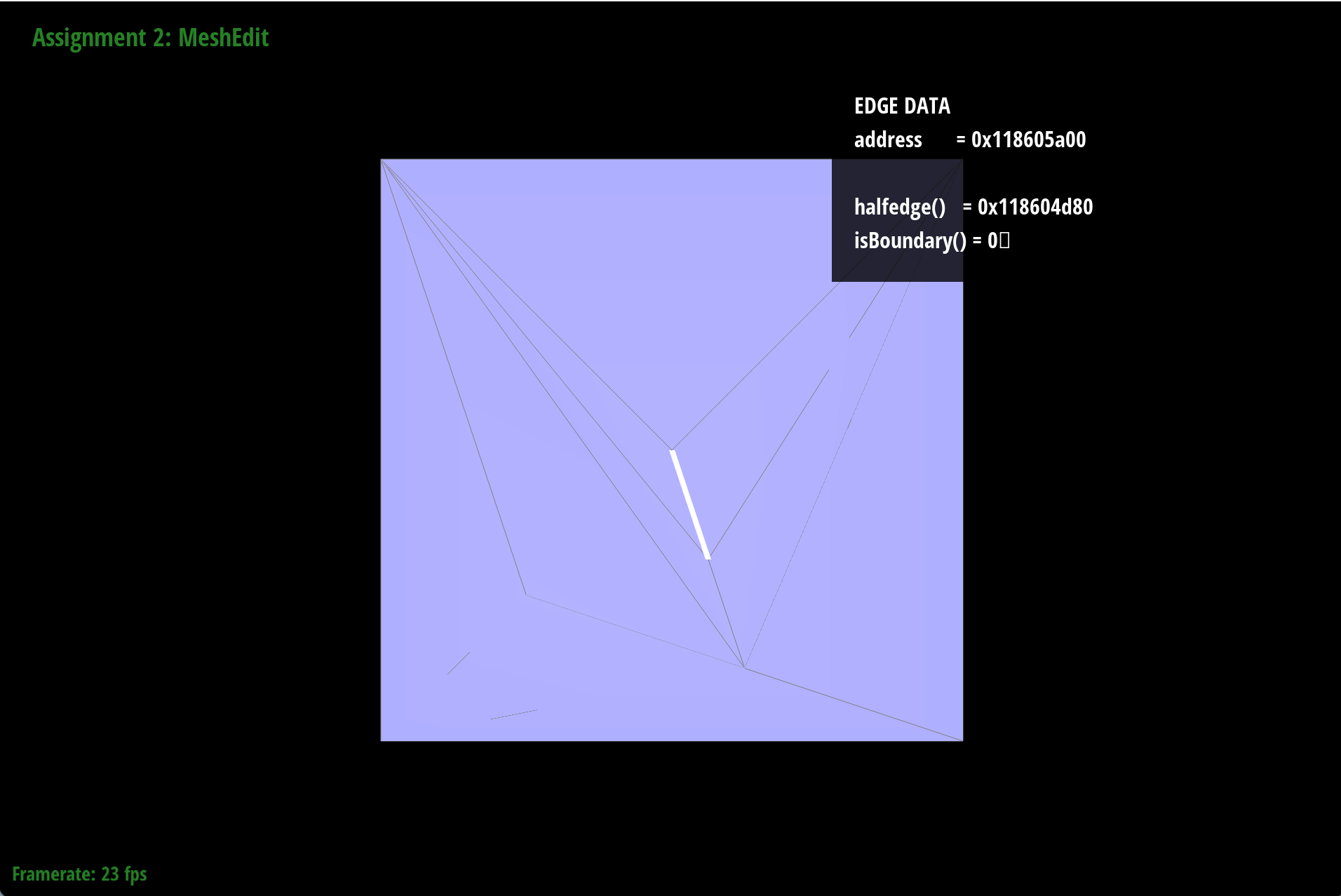
To perform an edge split, we first need to identify the edge we want to split and the two vertices that are connected by that edge. Then we will create a new vertex at the midpoint of the edge, and update the half-edge data structure by creating new half-edges and faces to accommodate the new vertex and the new edges that are formed as a result of the edge split.This is an example of the effect of edge split:

|
|
|
|
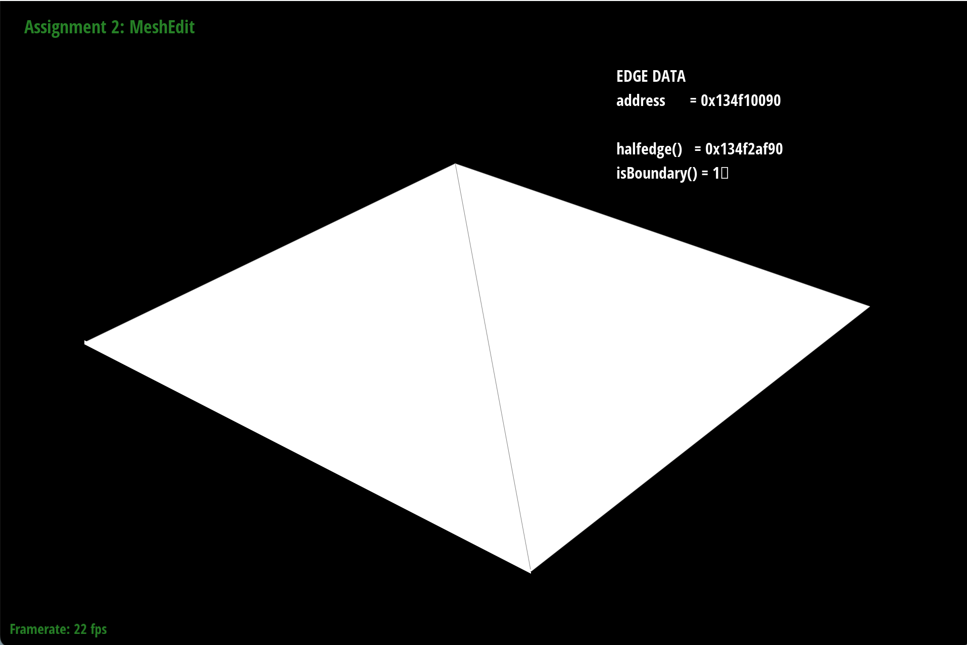
|
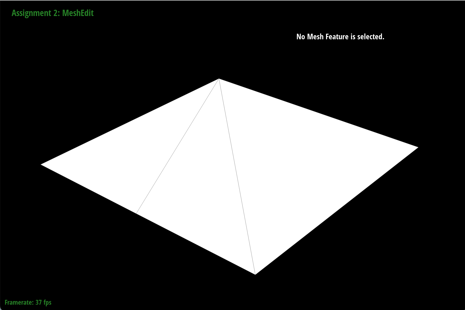
|
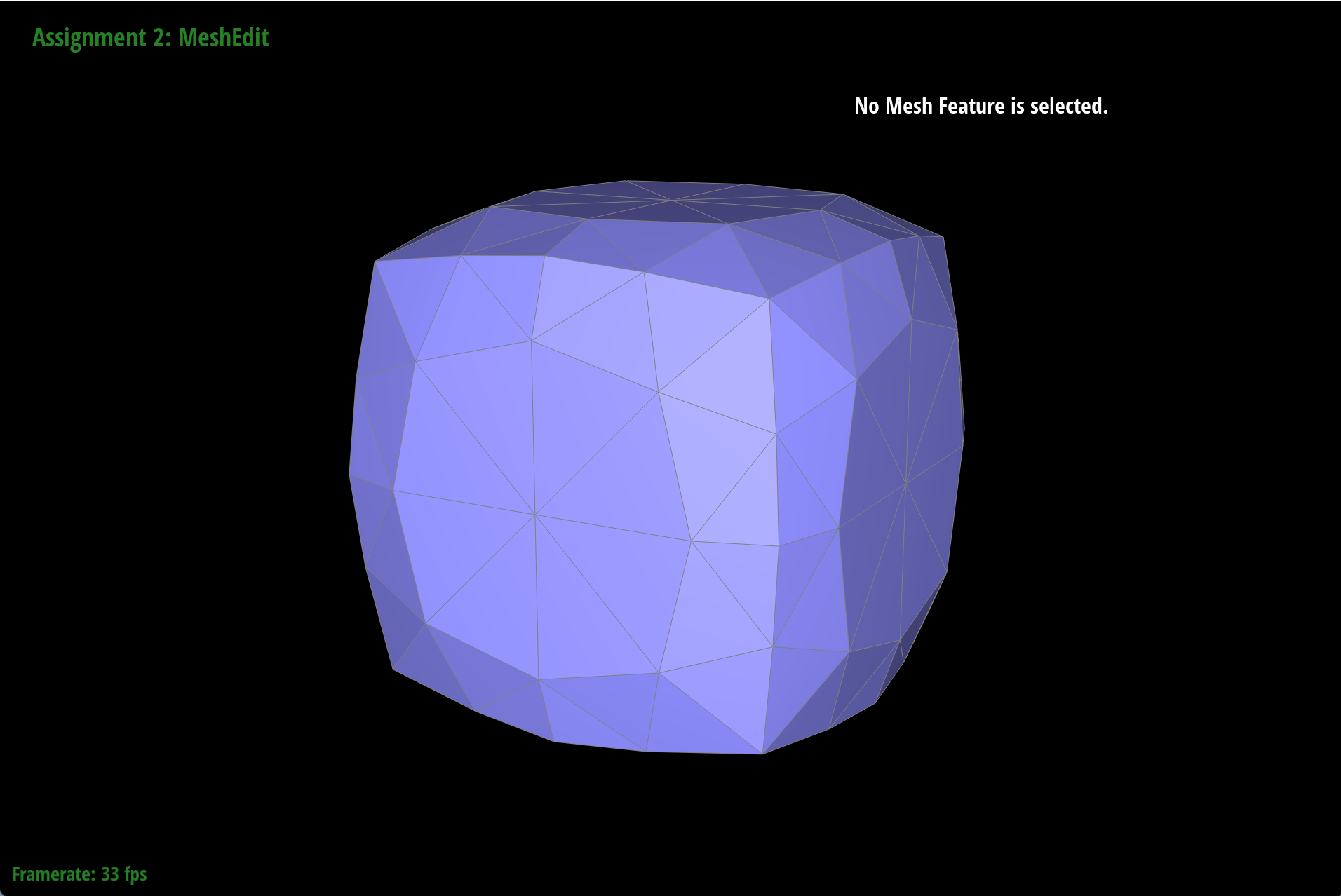
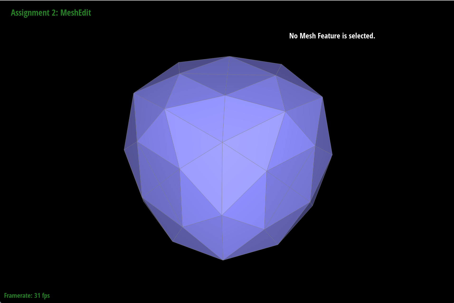
Part 6: Loop subdivision for mesh upsampling
To perform Loop subdivision for mesh upsampling, we will first calculate the new vertex positions for the existing vertices and the new vertices that will be created at the midpoints of the edges. Then we will create new faces by connecting the new vertices with the existing vertices according to the Loop subdivision rules, and update the half-edge data structure accordingly to reflect the new configuration of the mesh after subdivision.One of the results of applying loop subdivision for mesh upsampling is reducing the hard edges and corners of the original mesh. To preserve the overall edge flow and corners, we can apply pre-split to every edge of the original mesh before applying loop subdivision, which will help to maintain the shape of the original mesh while still achieving a smoother result after subdivision.
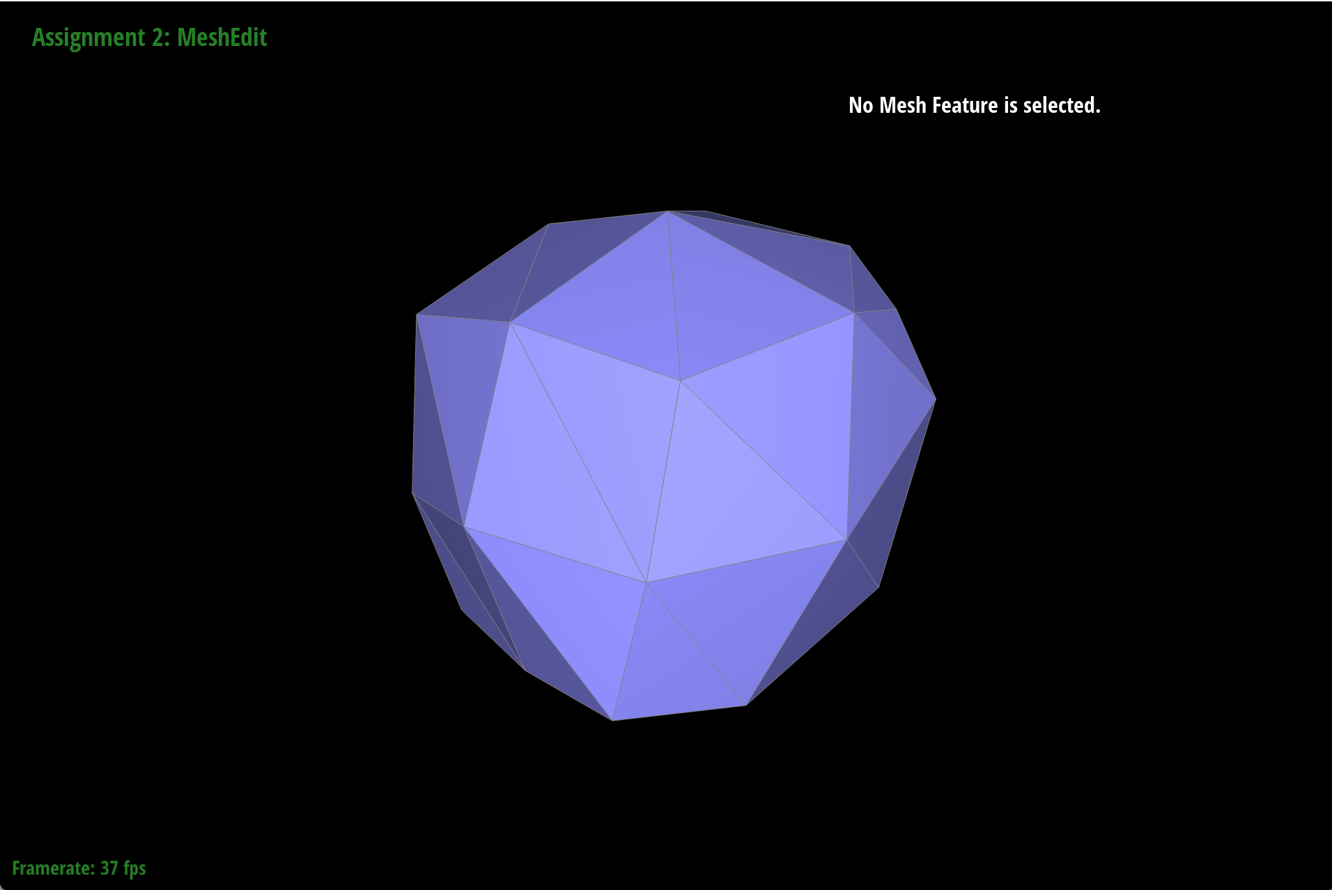
|
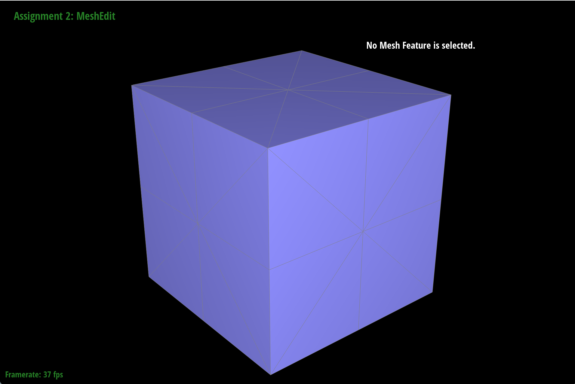
|
|
|
|
|
(Optional) Section III: Potential Extra Credit - Art Competition: Model something Creative
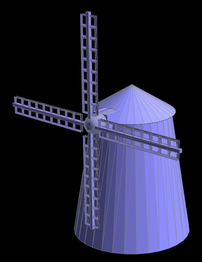
Finally, for the extra credit section, I created a windmill model using Blender and rendered it with the Bezier surface implementation in this homework. The windmill has a simple structure with a base, a tower, and blades, and it is a fun way to apply the concepts learned in this homework to create something visually interesting!