CS184/284A Spring 2025 Homework 4 Write-Up
Link to webpage: cal-cs184-student.github.io/hw-webpages-nadahameed/hw4/
Link to GitHub repository: github.com/cal-cs184-student/hw4-clothsim-nadahe4-1
Overview
For this project, I implemented a full cloth simulation. First, I implemented masses and springs to set up a cloth. Then, I added force and relationships between these springs and masses so that the cloth could move realistically. Then, I added handling for collisions with other objects. I checked intersections with a sphere/plane so that the cloth would interact correctly with them. Then, I made sure the cloth could handle collisions with itself (ie layering over itself). I also implemented different shaders like Blinn Phong and Toon shading to change how the interaction looked. Finally, I added some extra features, like wind's effect on the cloth. Overall, I was able to create a physically realistic cloth renderer with different functionalities!
This assignment was pretty fun. The point mass data structure was interesting, and there was a lot I could do with it to implement different features. Also, the springs between point masses were a cool concept to me. When I worked on adding wind, it was cool how you could see the effect of different forces on the point masses (ie gravity vs spring force vs wind force). It was satisfying to see the cloth fall on the sphere realistically! I had the most fun with the shading and textures. I was able to implement different textures onto the sphere and cloth, and you could change how strong those height displacements are, which was fun to play around with. I also had fun making a custom shader. In 3D animation software, I learned how to implement toon shading, and it was fun to implement it here as well.
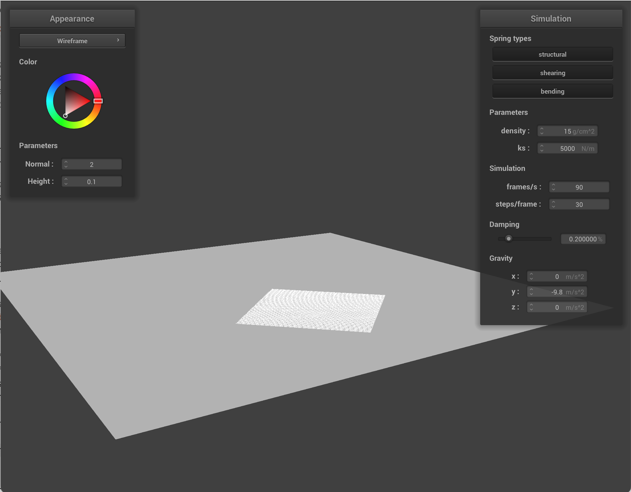
Part 1: Masses and springs
I built a grid of masses and springs.
First, I built the masses. The code uses a data structure called a PointMass, which represents a particle of the cloth at a single 3D position. Each point mass stores its current and previous position, accumulated forces, and whether it is pinned. Springs connect neighboring point masses to make the cloth behave like a surface. To build the grid, I created num_width_points by num_height_points masses via nested for loops. At each point, I created a point mass. Then for each point mass, I computed what their x and y position would be, scaling it to fit the grid. Then, there were some specific checks to do. If the orientation was horizontal, I set the position of the point mass to be (x, 1, y). If it was vertical, I set the position to be (x, y, [a random number from -0.001 to 0.001]). Then, I checked point mass's (x, y) was within the pinned vector (by looping through): if so, I set the point mass boolean pinned to be true (false by default). Finally, I stored the point masses in the point_masses vector in row-major order.
Next, I created springs between these point masses. To create a spring, I used pointers to the two point masses, and defined what type of spring it would be. I looped through the point masses freshly made in the previous step, and then checked the neighboring point masses to make springs. For structural springs, I checked the left point mass and the above point mass, and if they were within bounds, I created a structural spring. For shearing springs, I checked the upper left point mass and the upper right point mass, and if they were within bounds, it was a shearing spring. Finally, for bending springs, I checked the point masses 2 to the left and 2 above, and if they were in bounds, I created a bending spring.
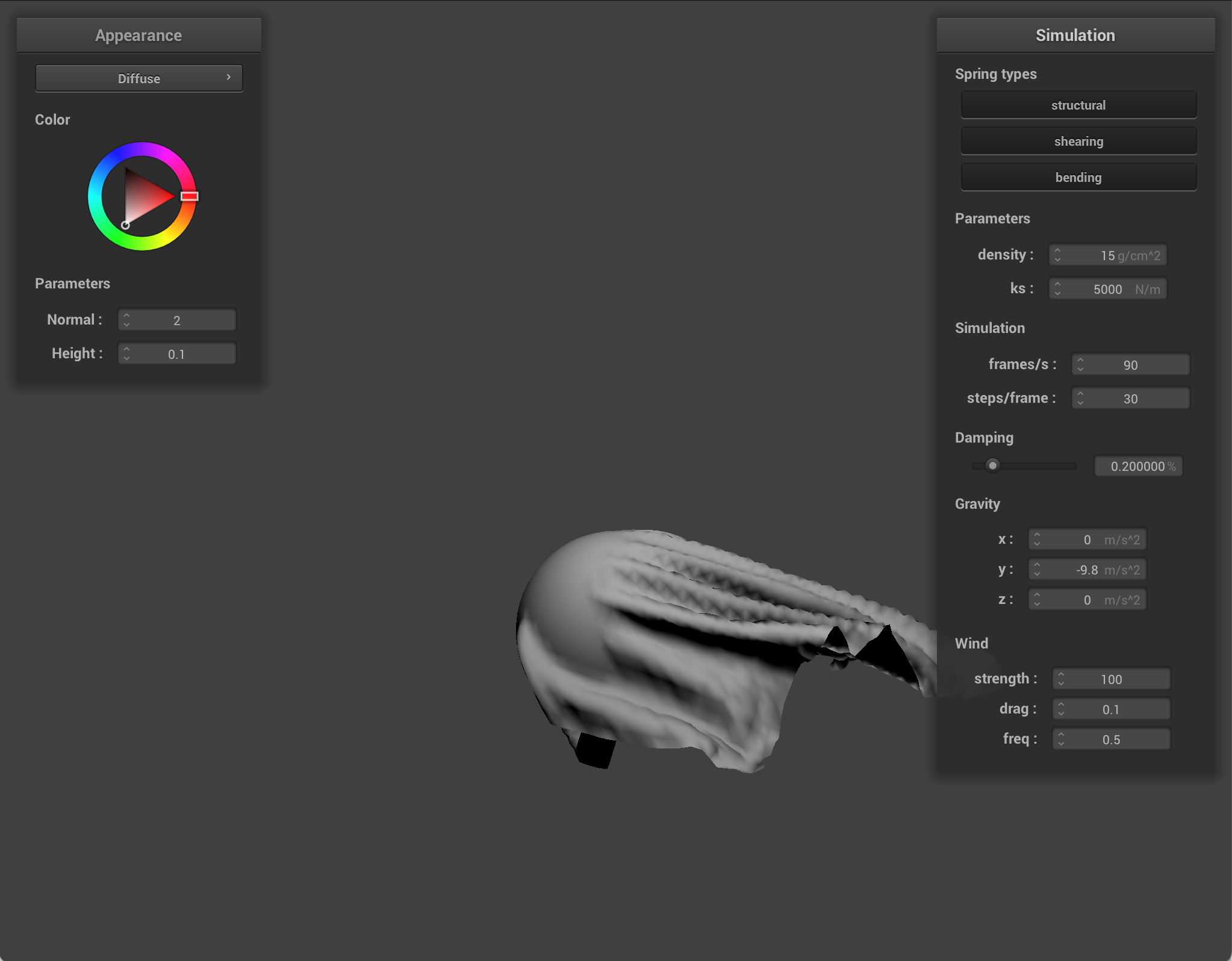
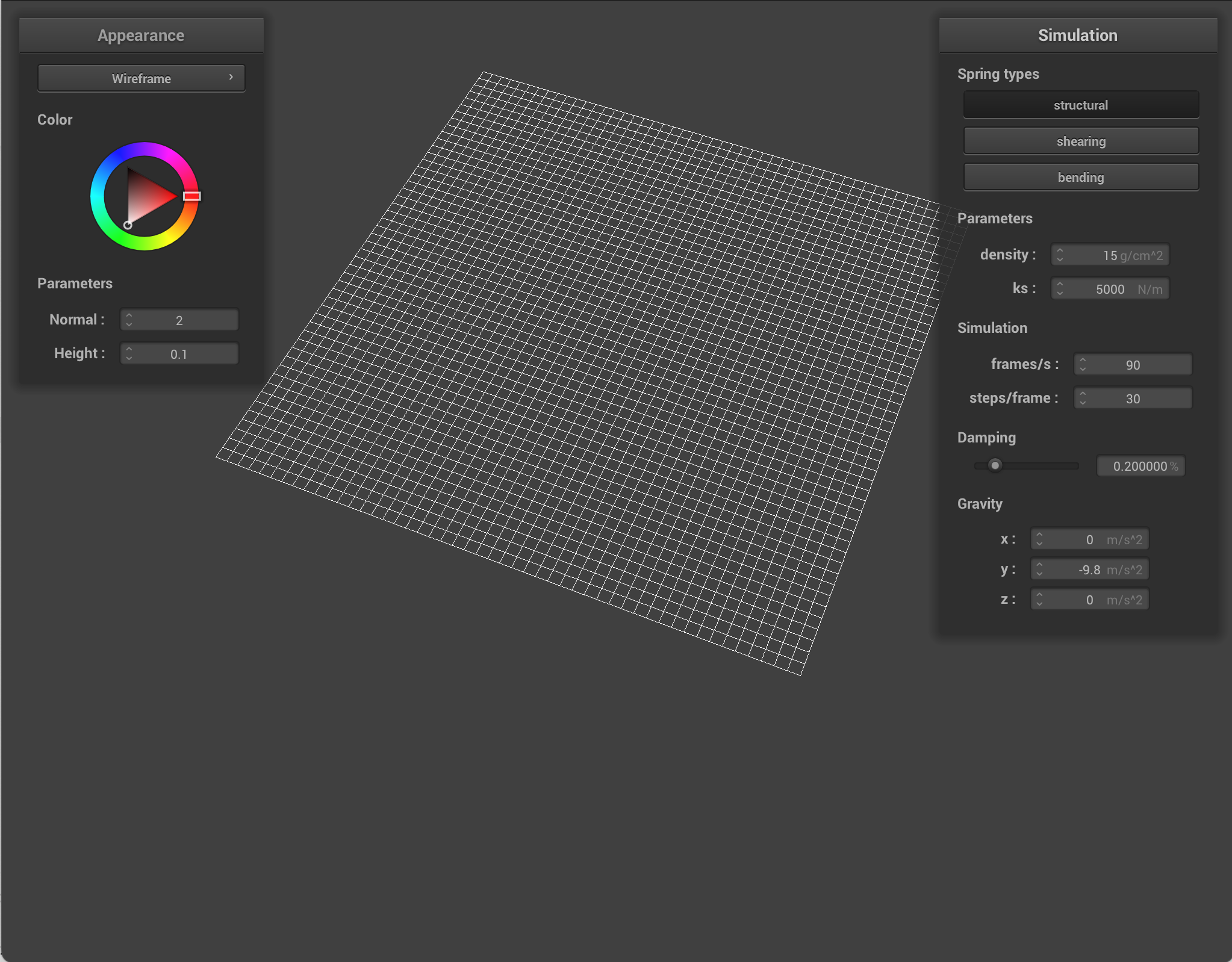
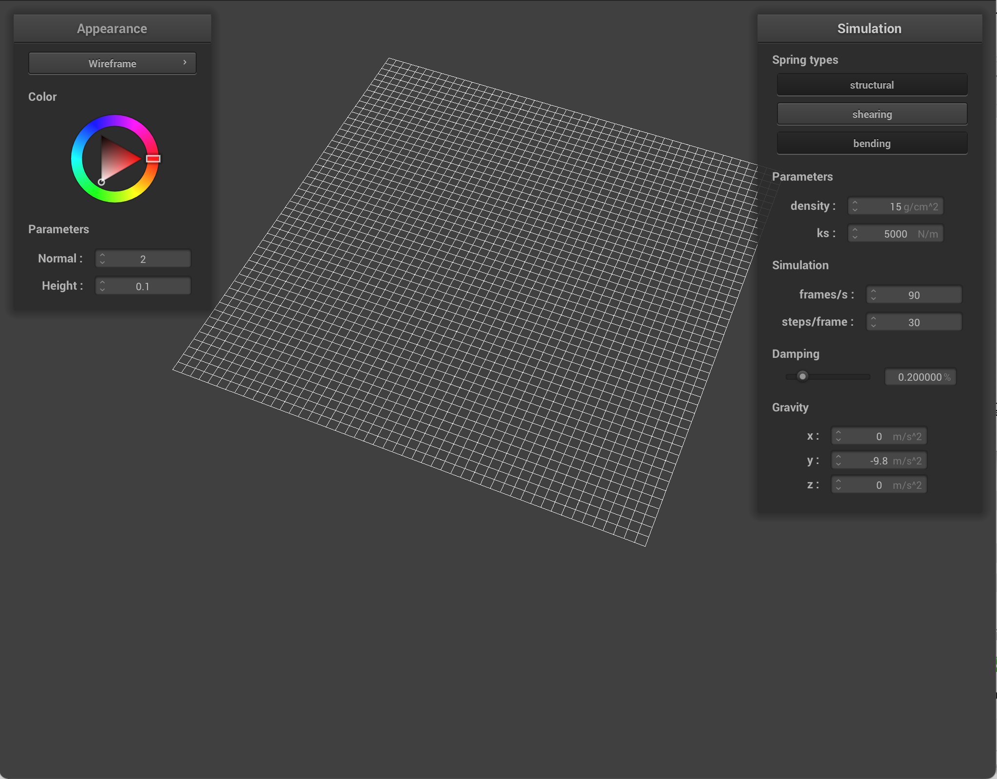
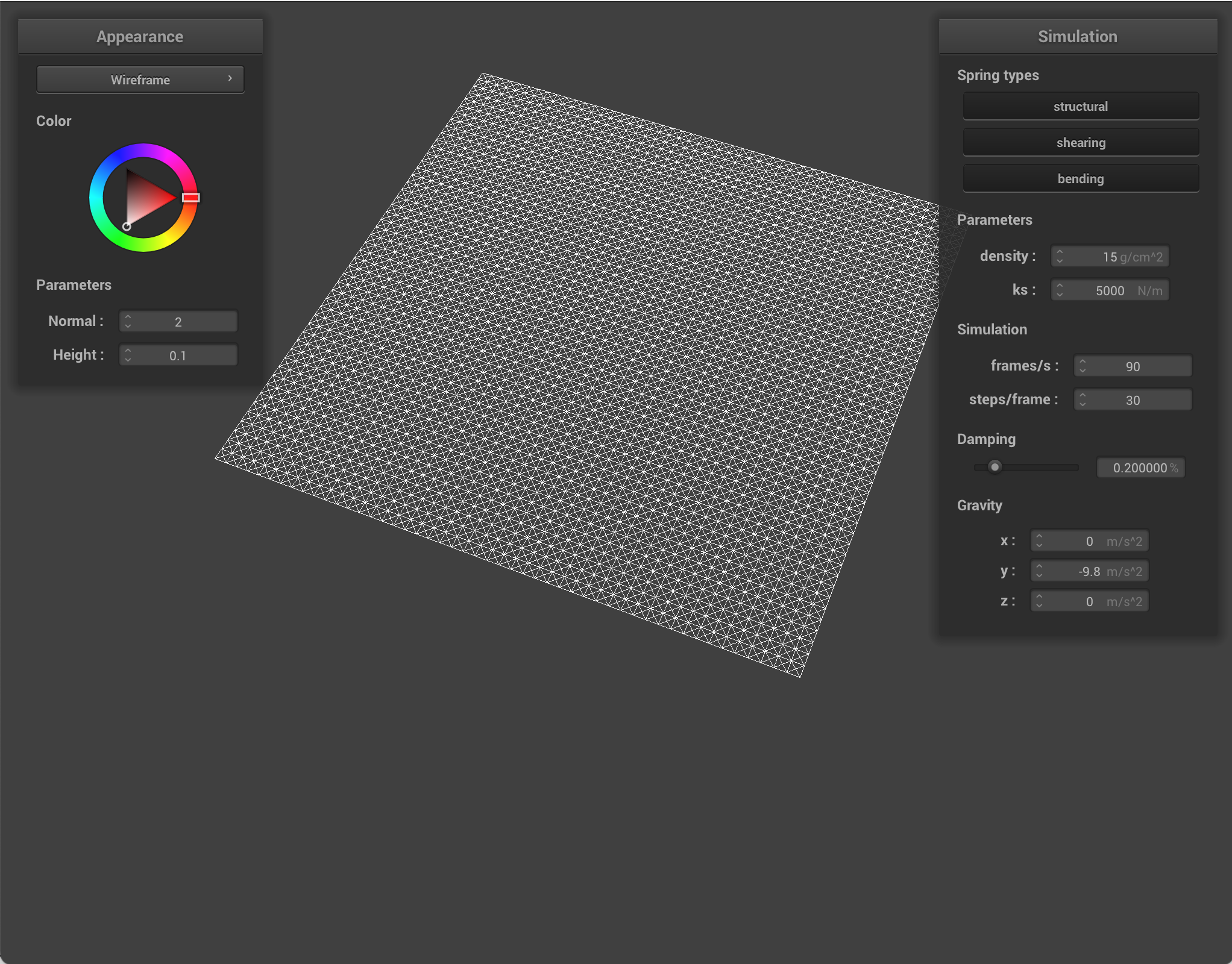
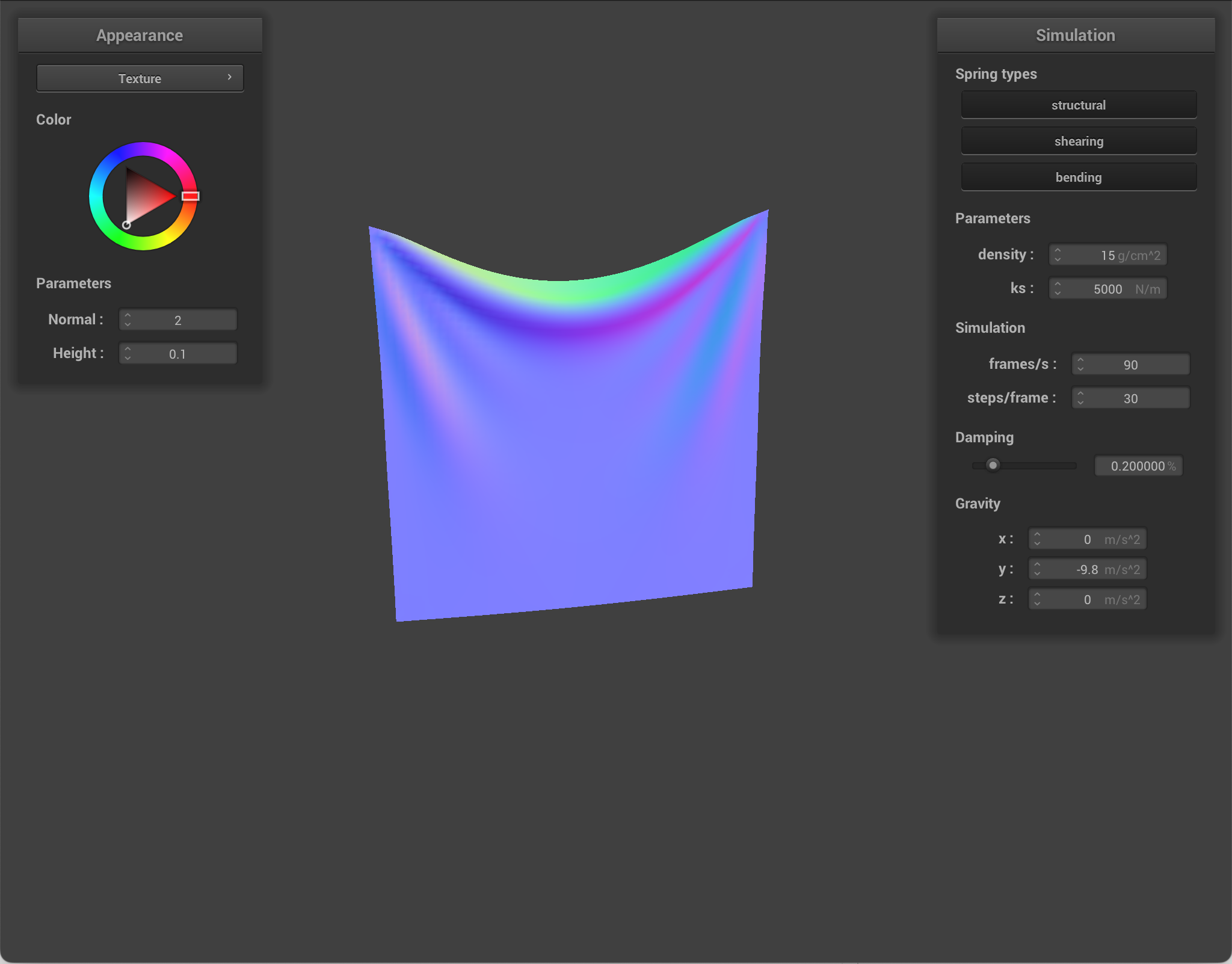
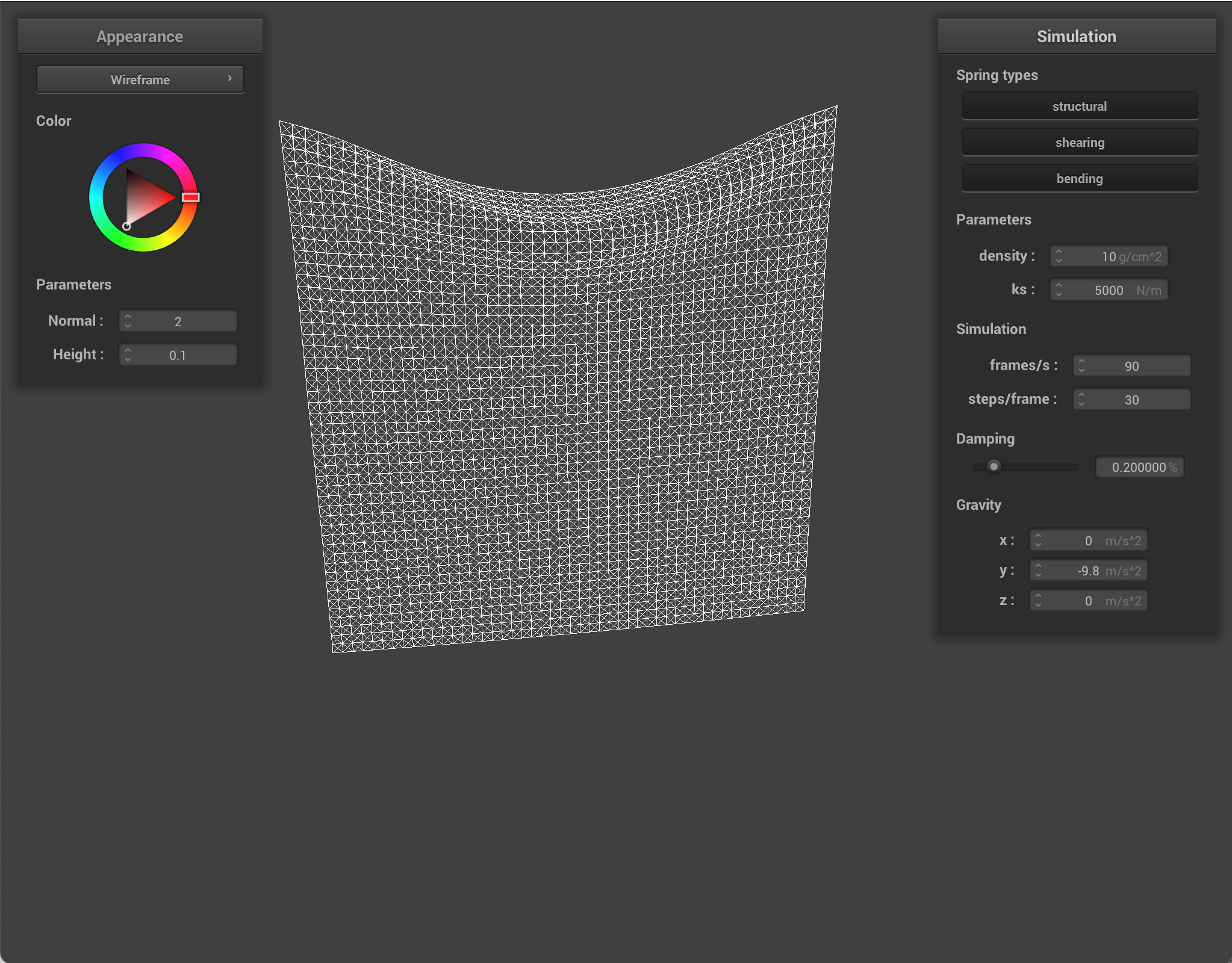
Here is the flat sheet with certain springs shown/hidden.
|

|
|
|
Part 2: Simulation via numerical integration
First, I computed the total force acting on each point mass. I did this by resetting pm.forces at the start of each call for all the point masses so there were no extra forces. Then I computed the total external force using F=ma. I accumulated the acceleration, and then multiplied by the mass (which was already done for us) to get the total external force. Then, I applied the spring correction force on each spring. Depending on the type of spring and whether that constraint was enabled, I computed the force with Hooke's law. Finally, I applied the force to one point mass, and the opposite force to the other.
Next, I used Verlet integration to compute the new point mass positions. For all the point masses, if it wasn't pinned, I used Verlet integration (including damping) to calculate and update the new position, and updated the point mass's last position.
Finally, I applied a constraint such that the spring didn't change in length mroe than 10% per time step. For each spring, I checked to see if the length was greater than 110% of the rest length, and if so, I applied certain corrections. If neither point masses were pinned, the correction was split evenly between the two. If only one was pinned, the other received the full correction. If both were pinned, nothing was done.
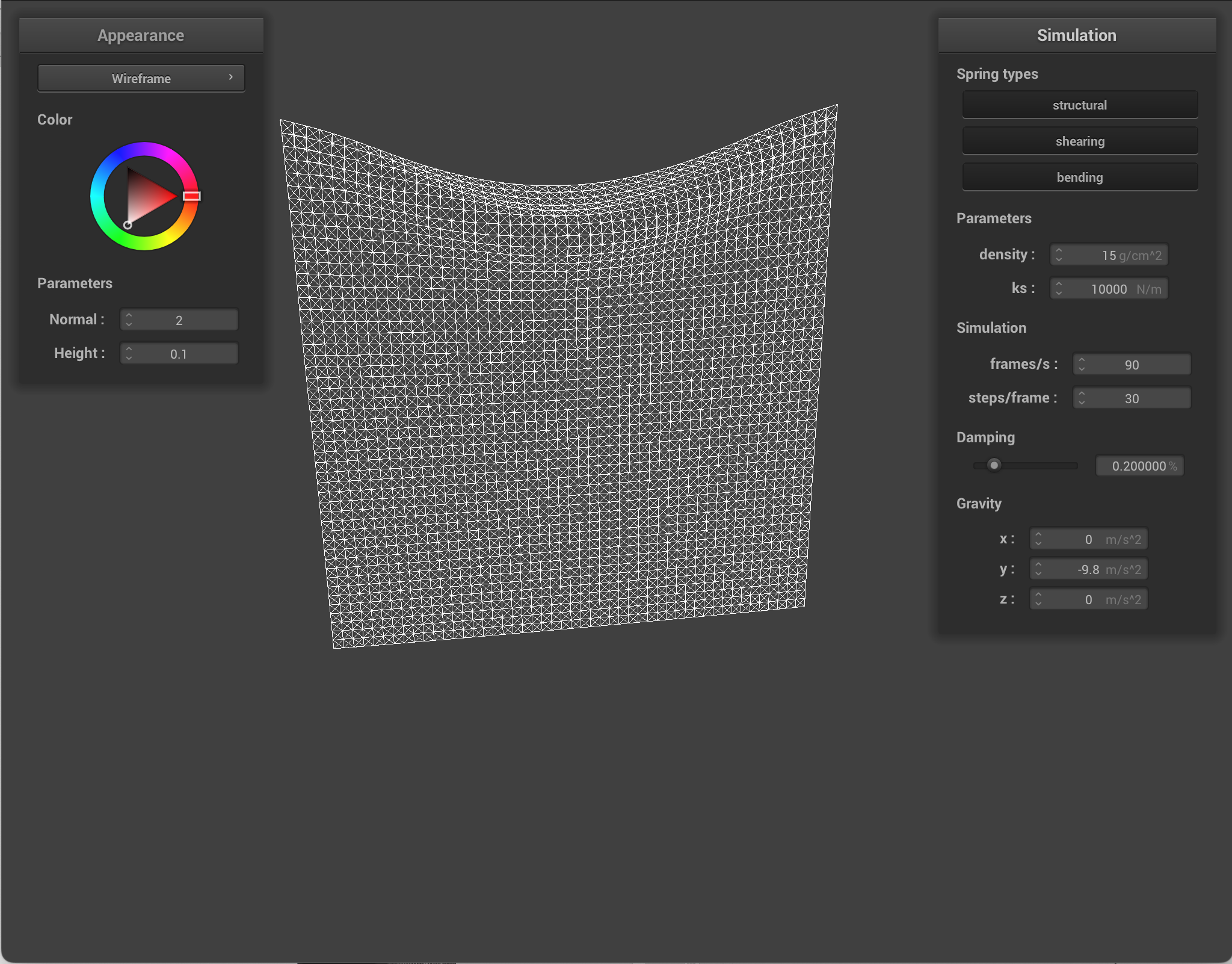
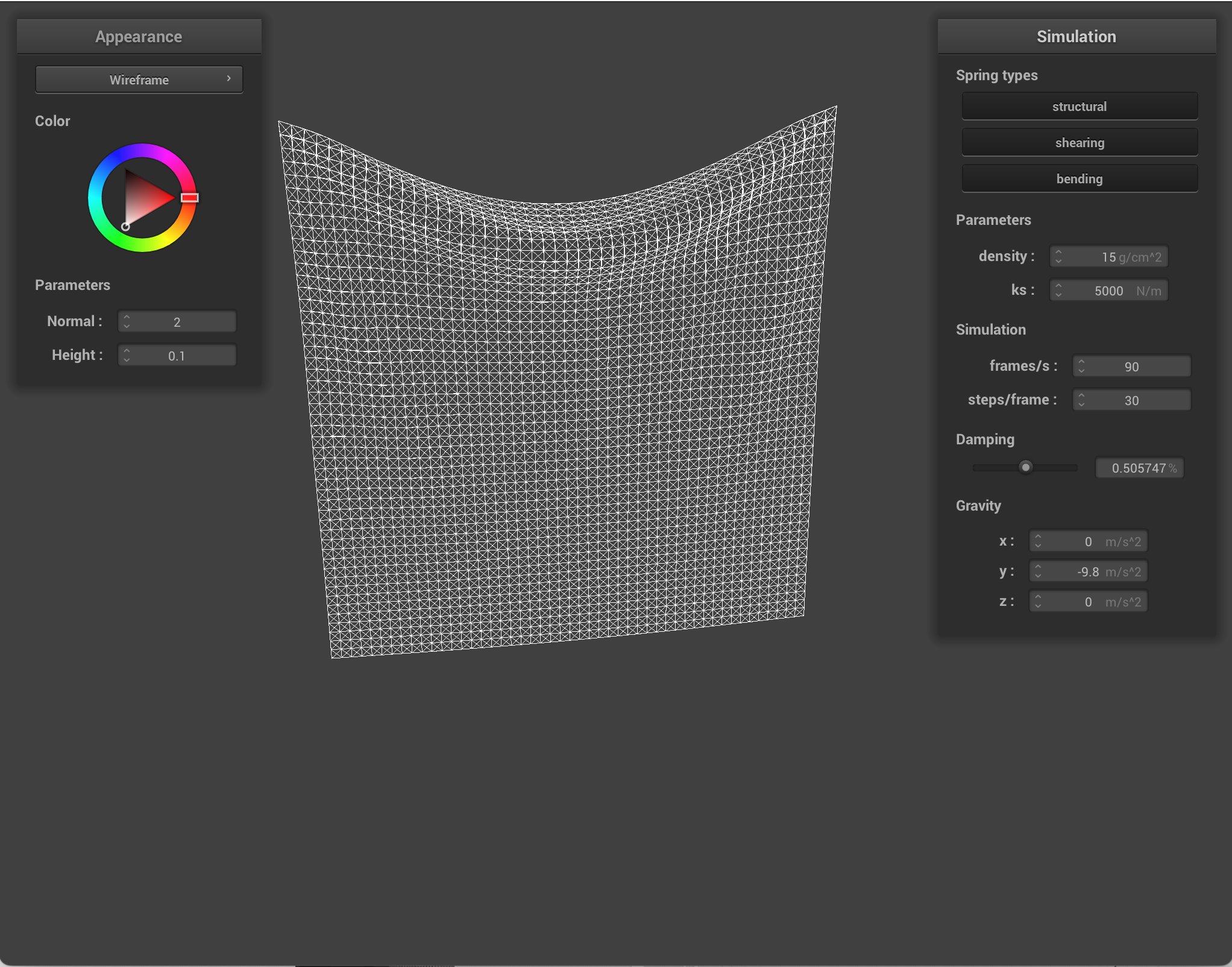
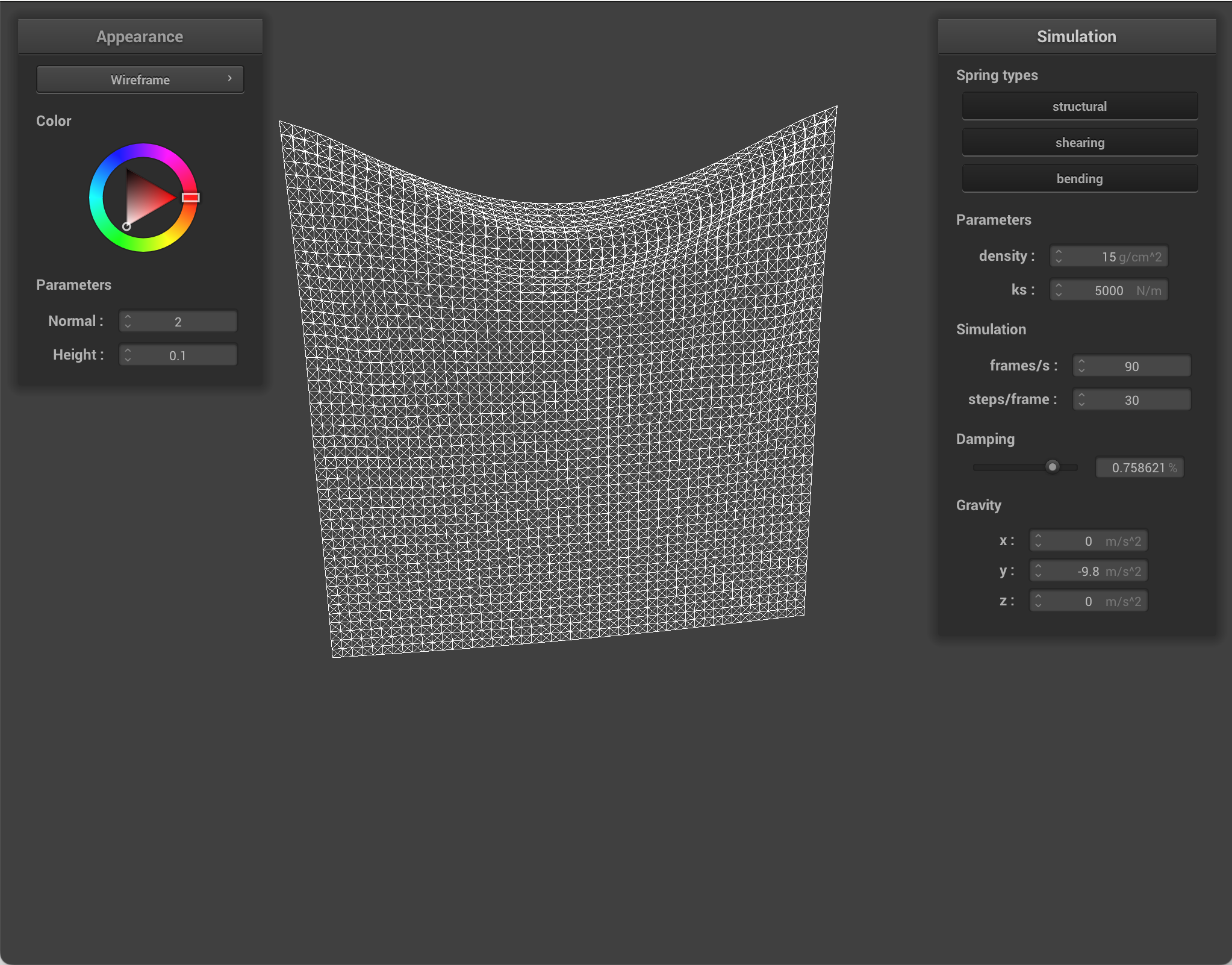
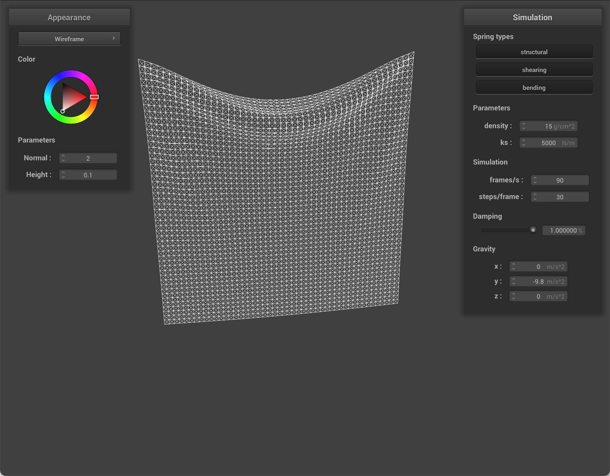
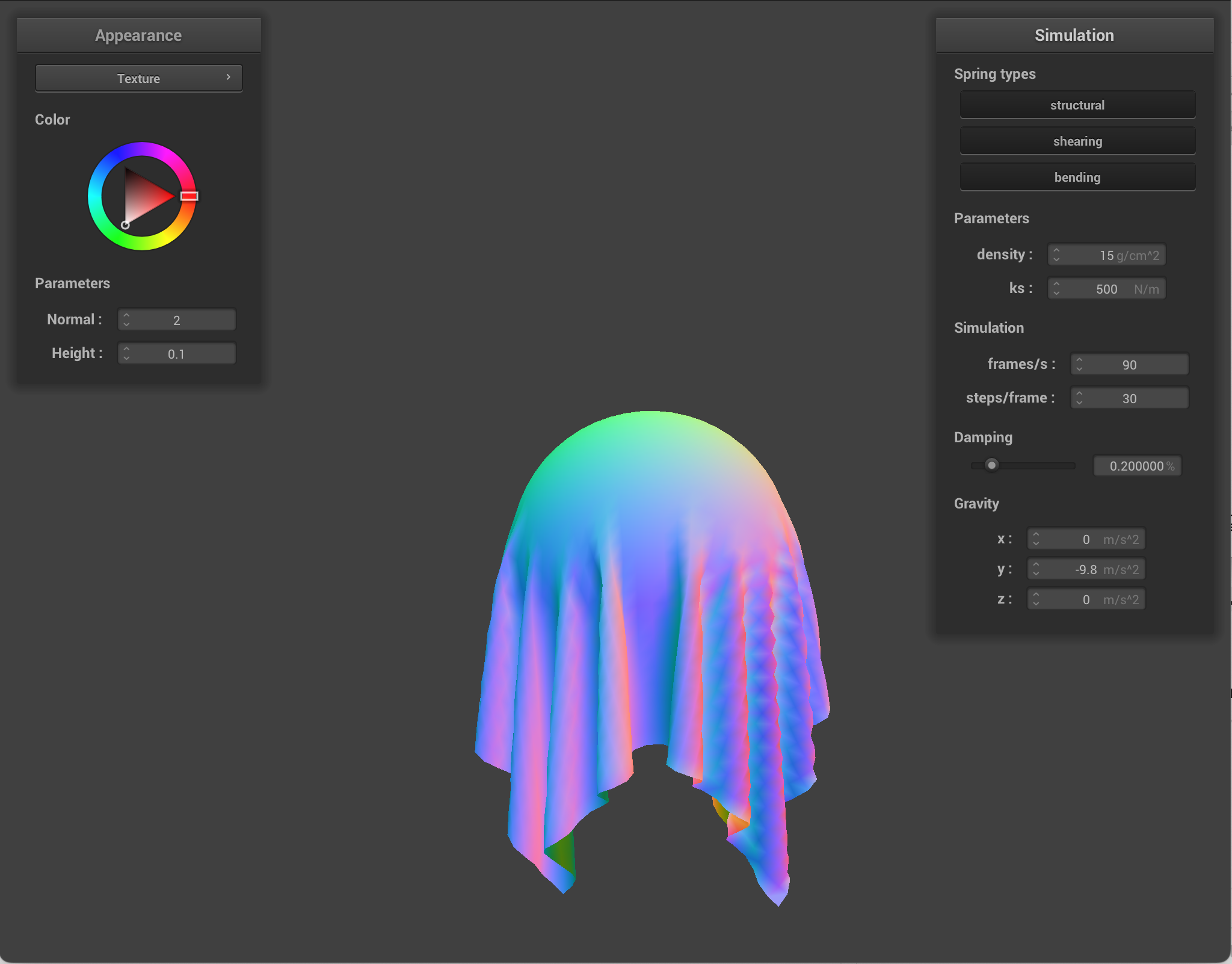
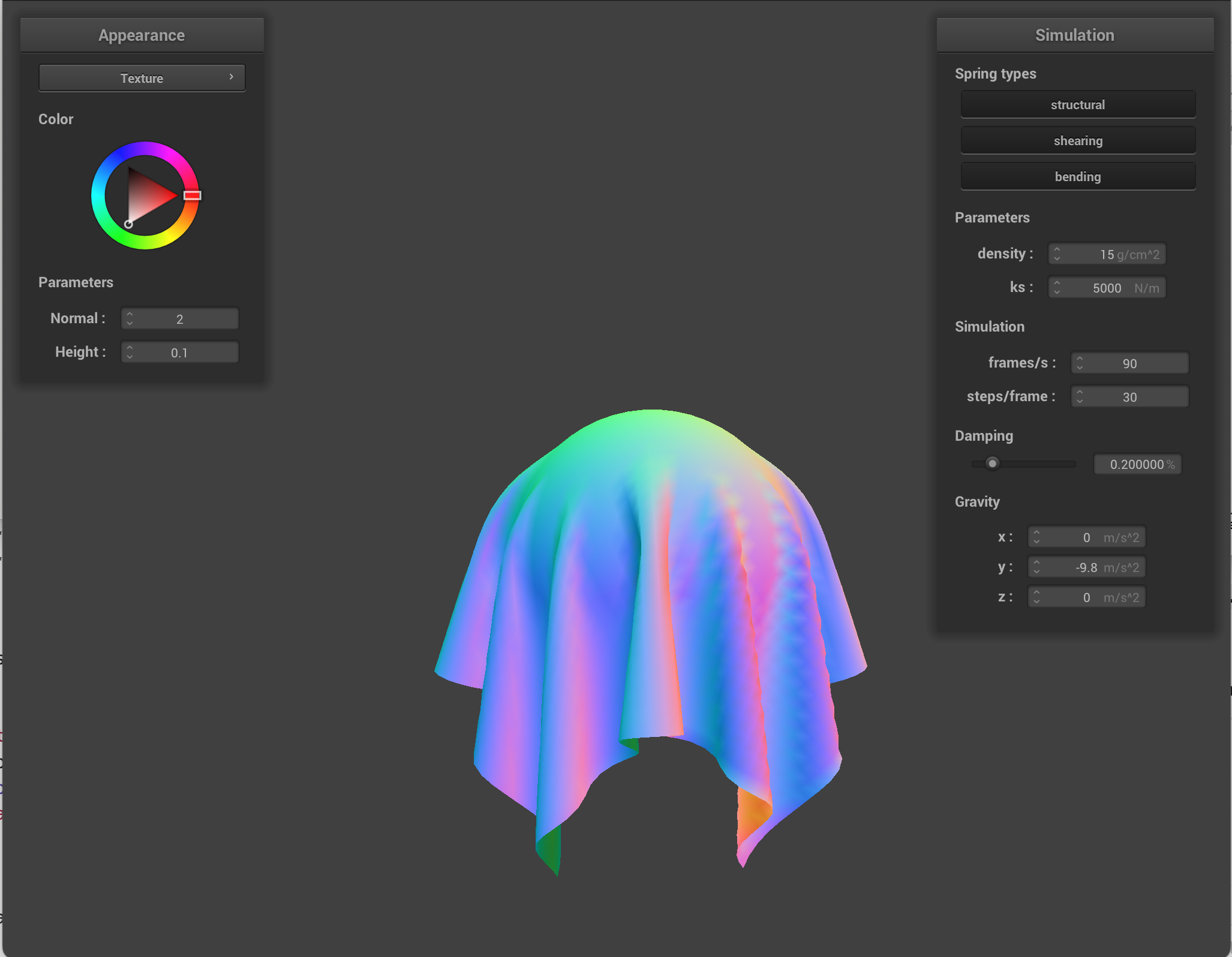
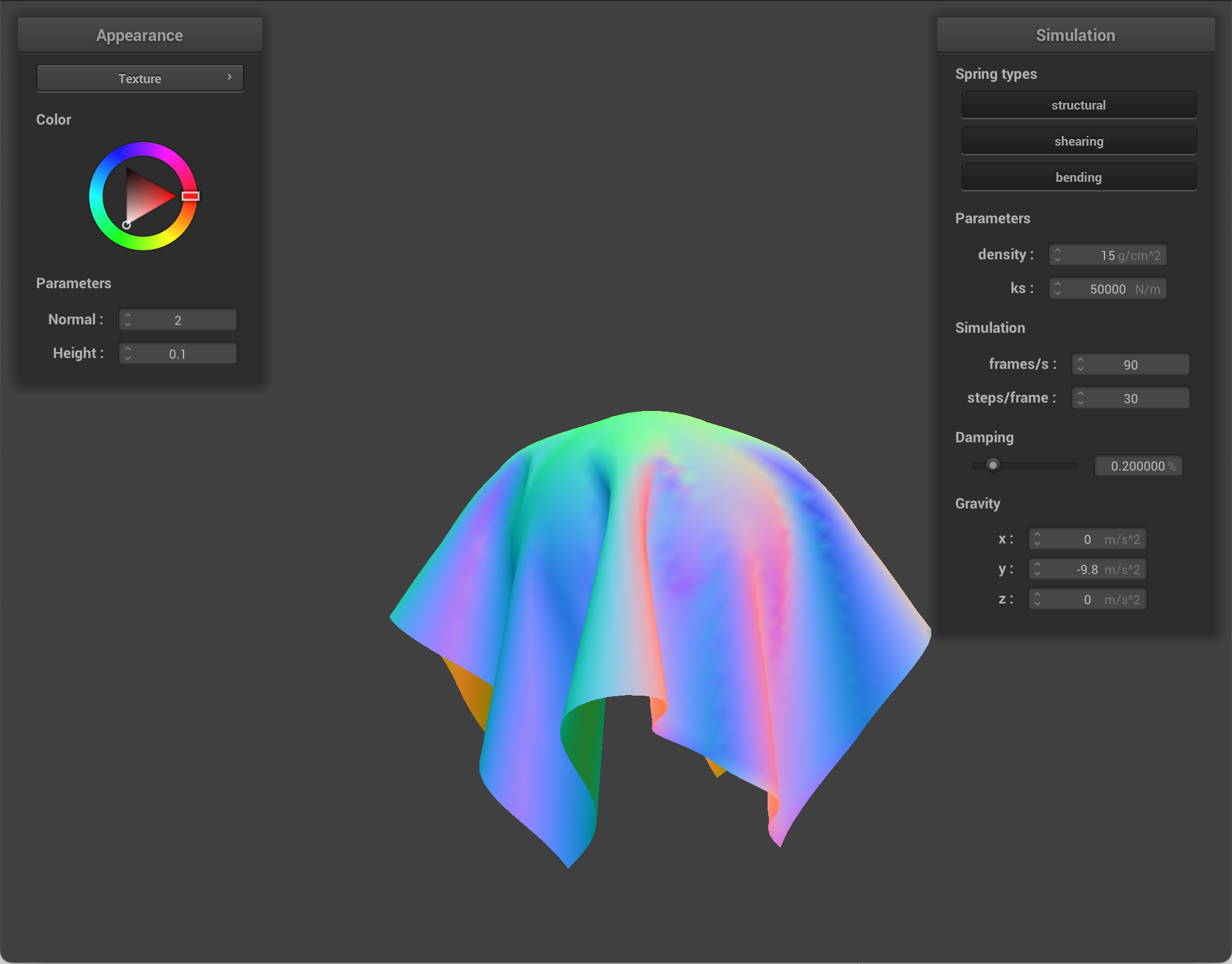
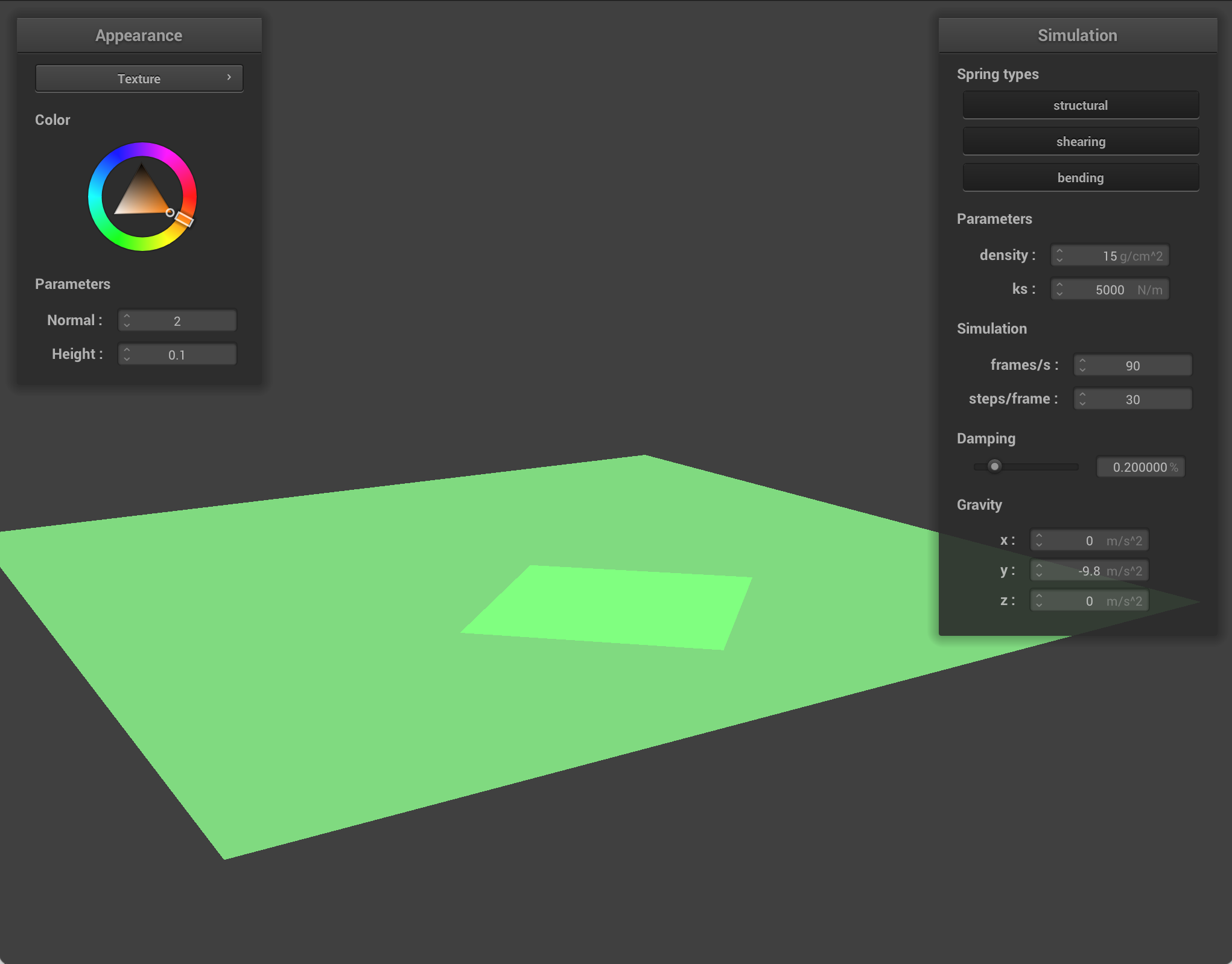
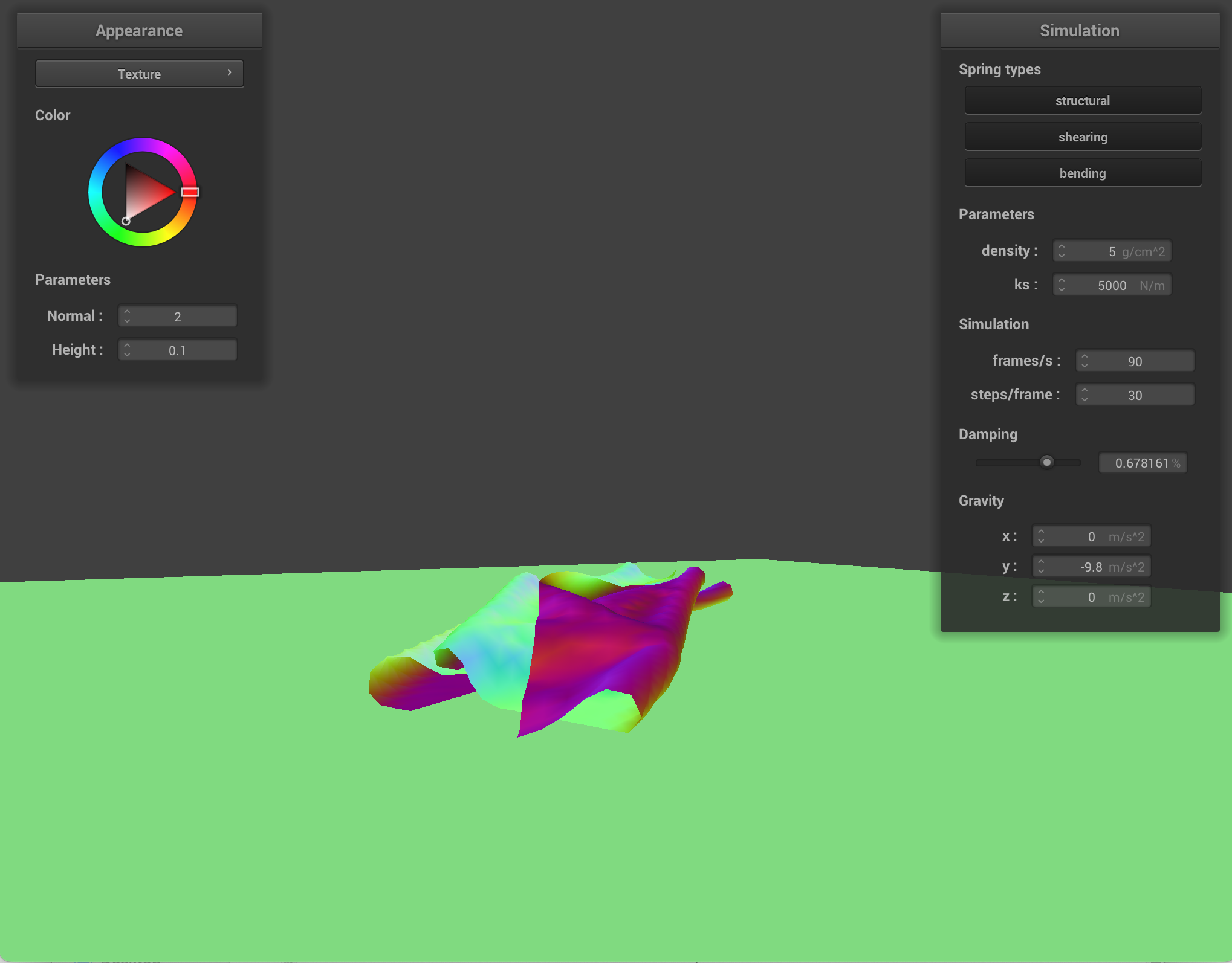
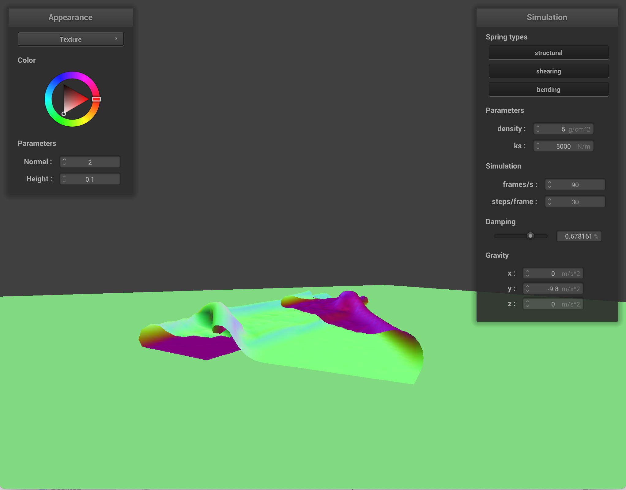
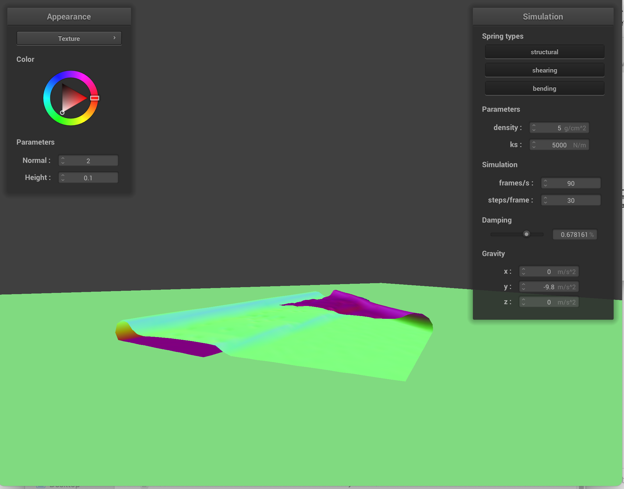
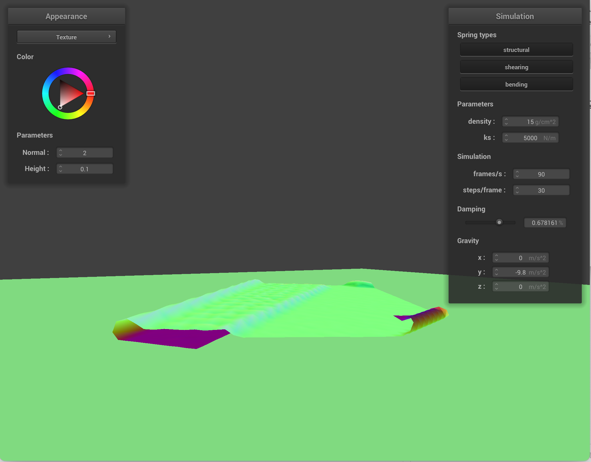
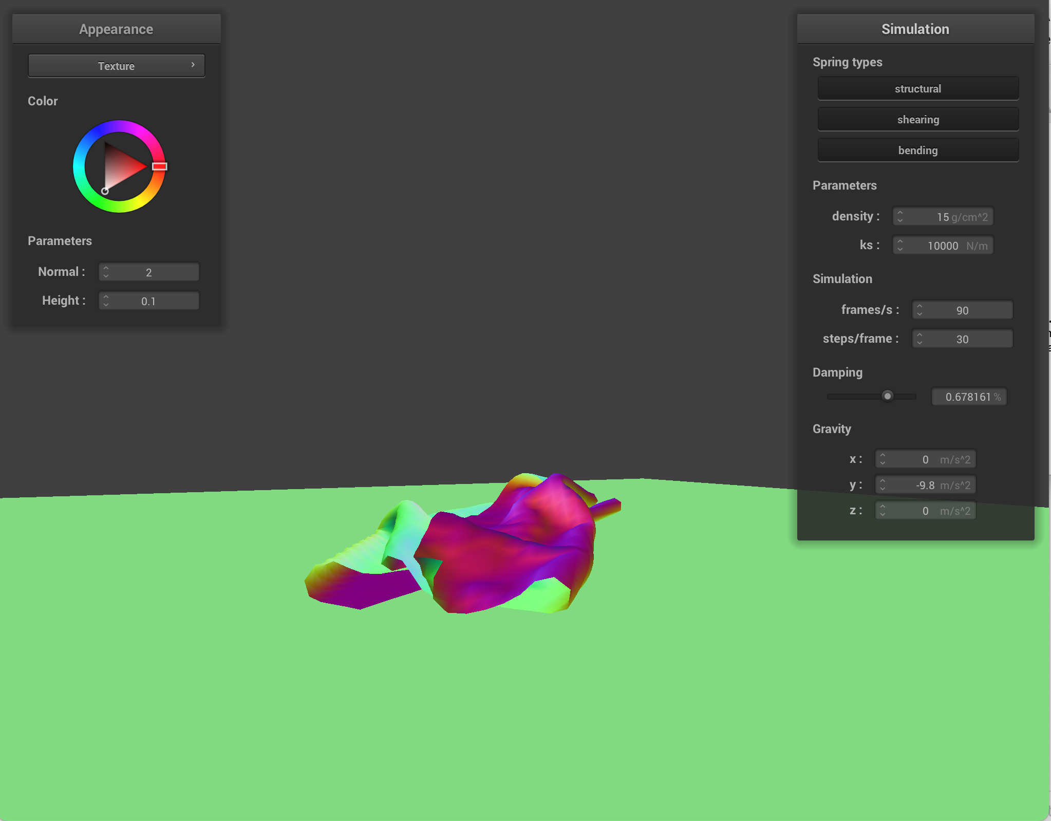
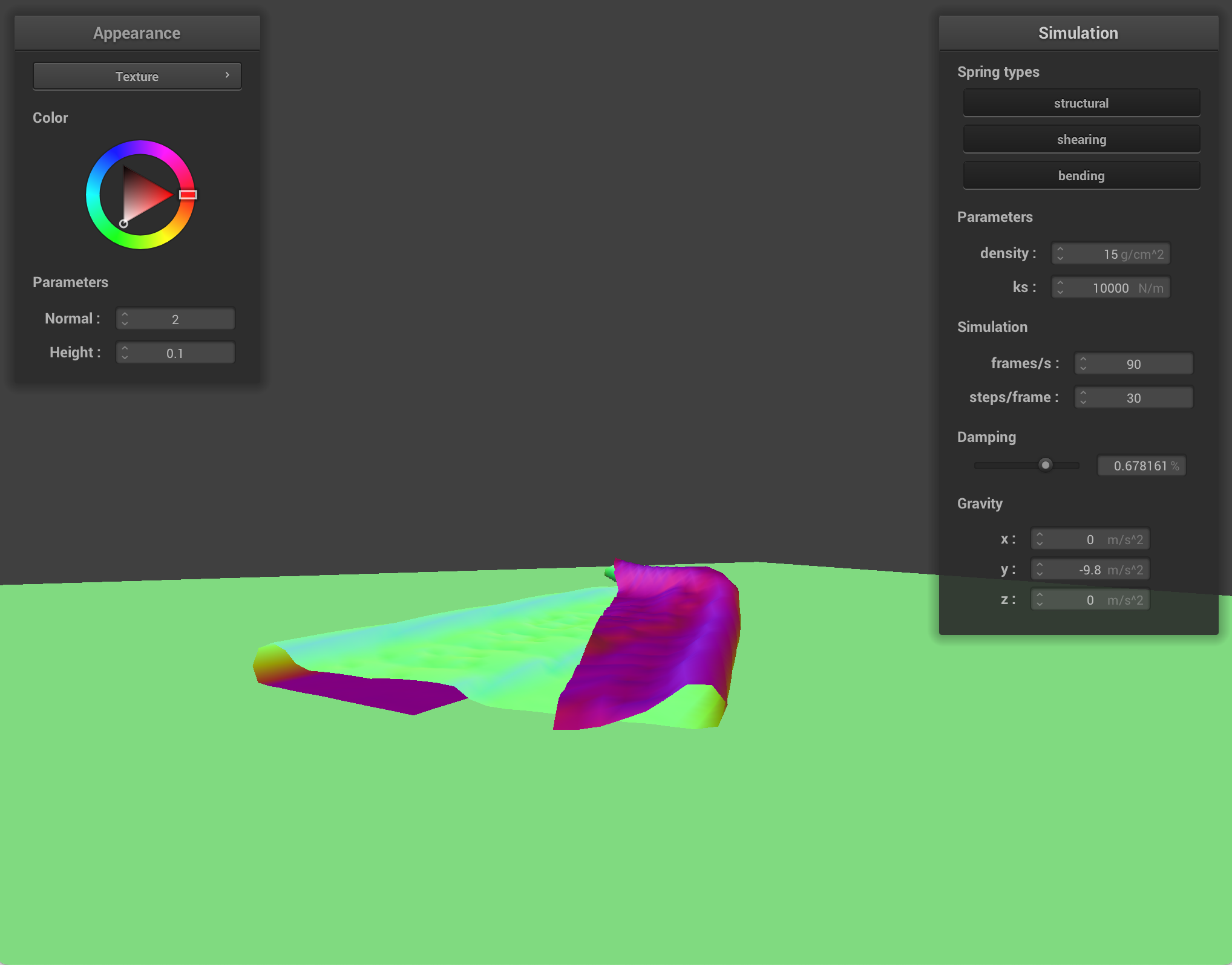
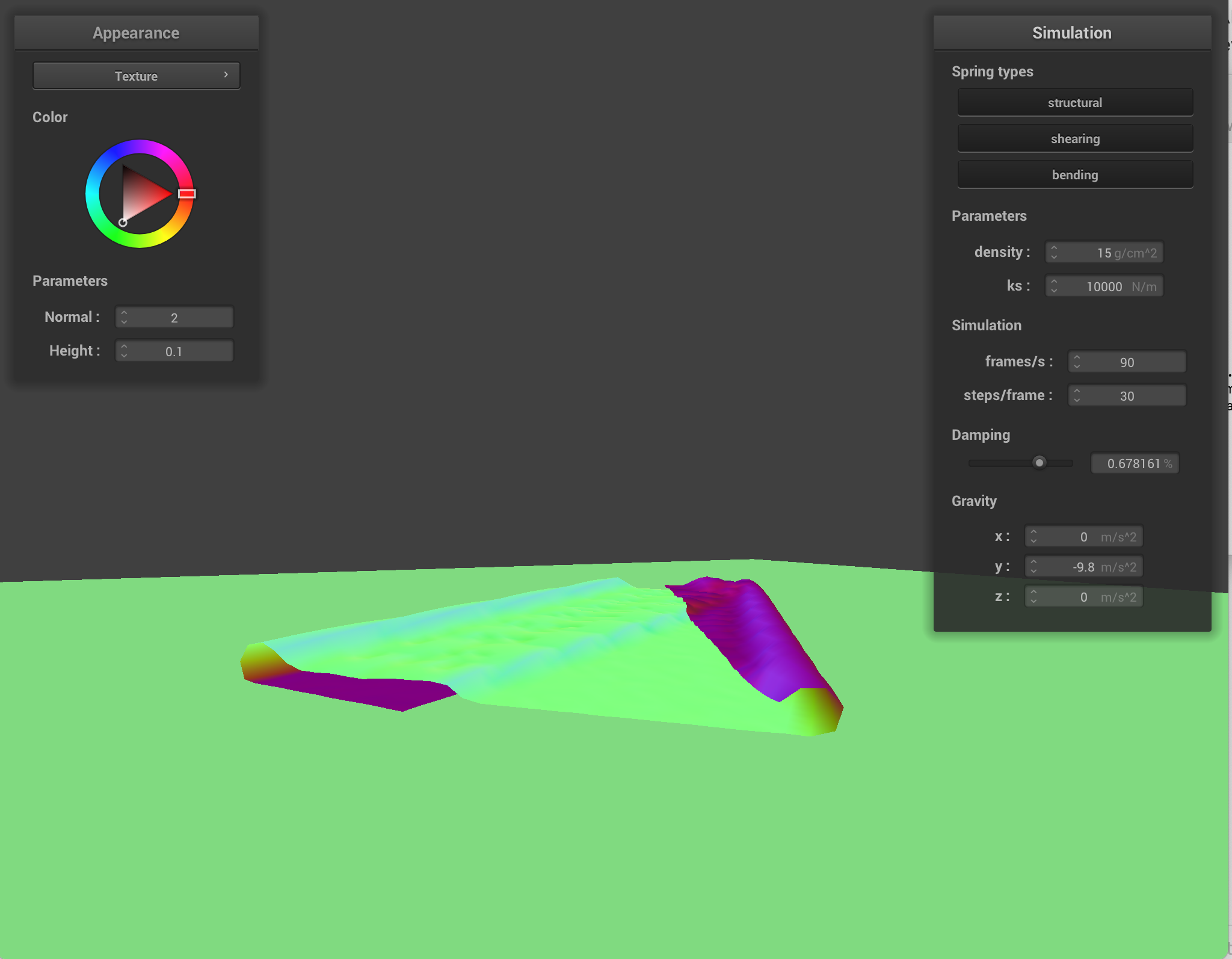
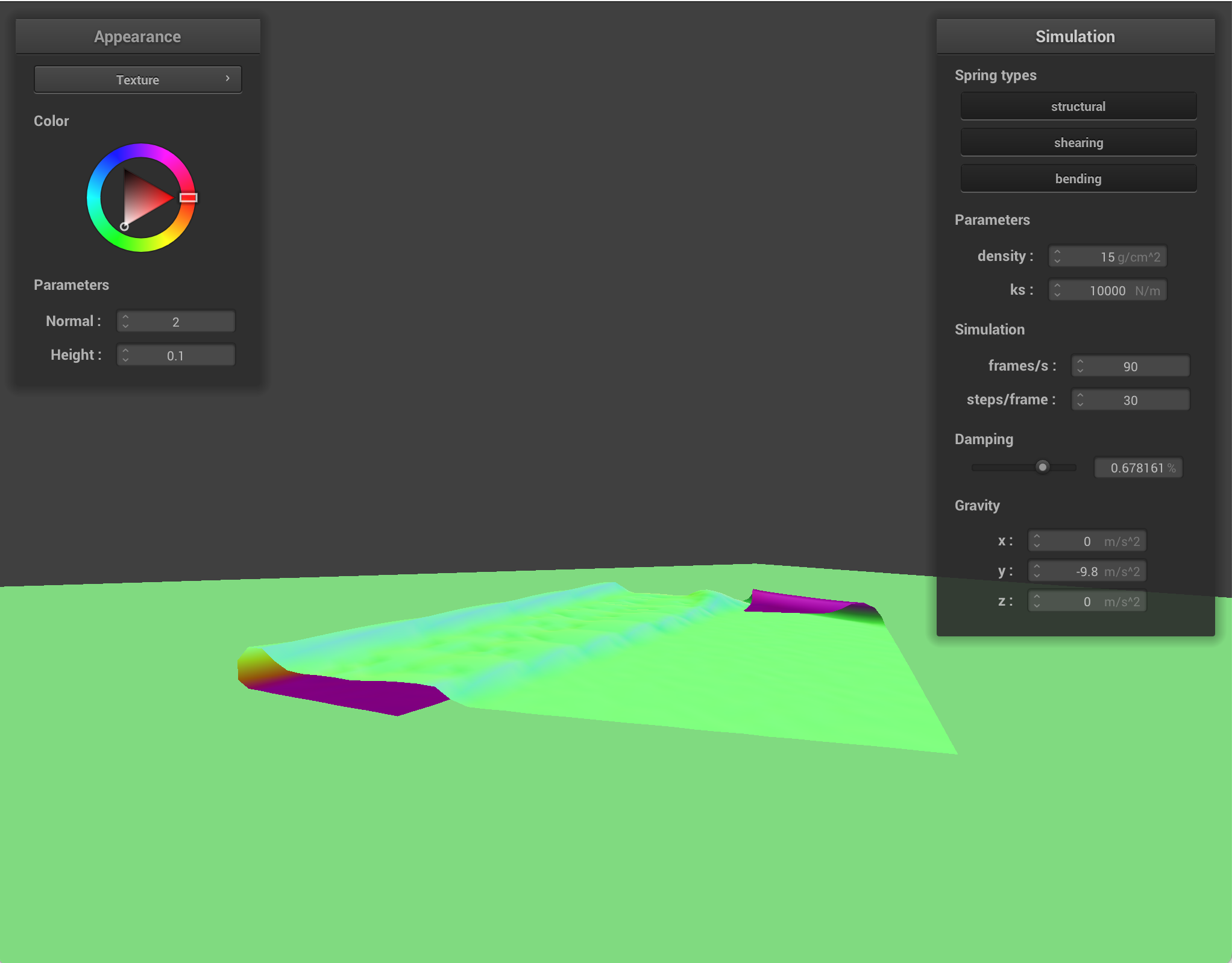
Difference between changing parameters:
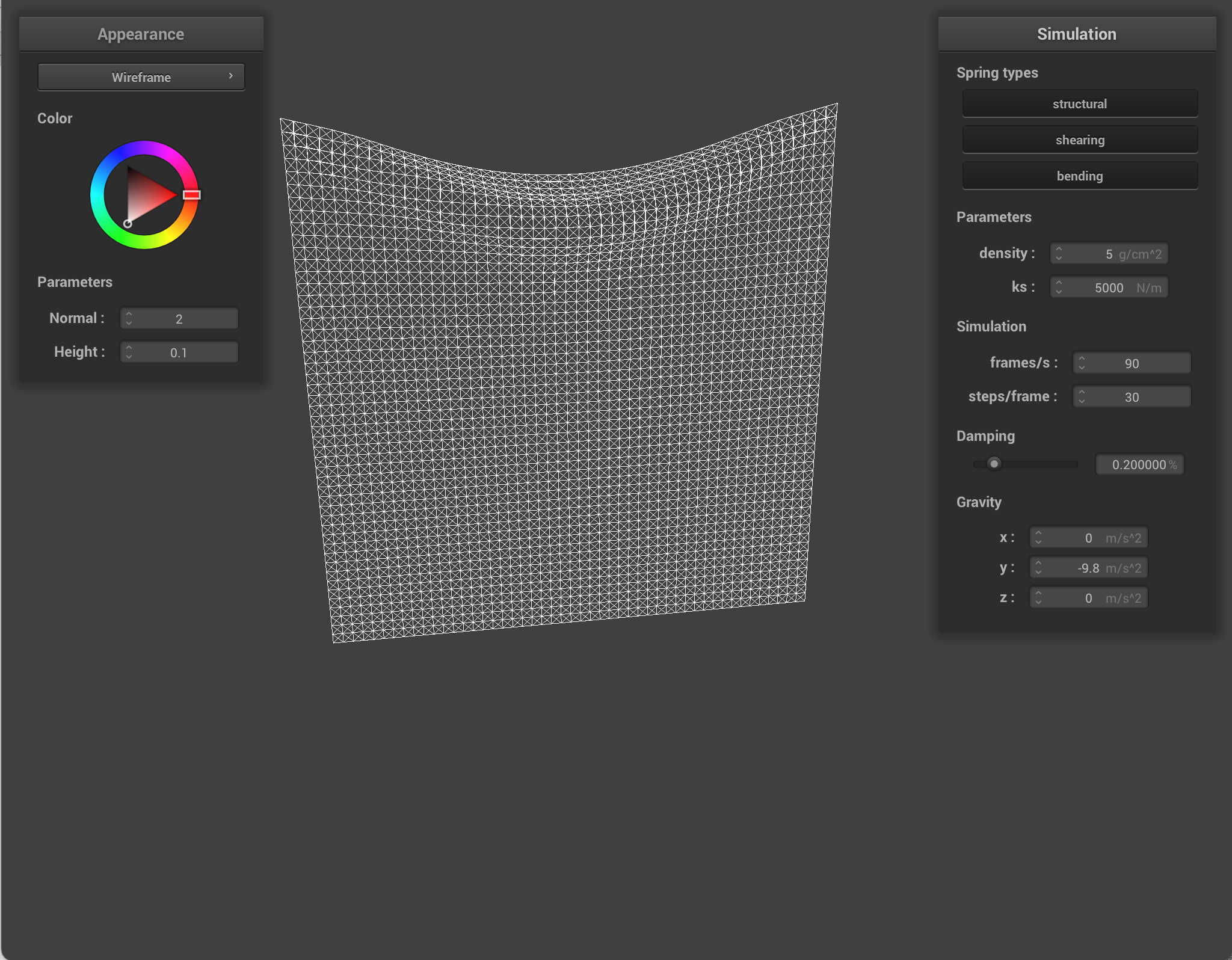
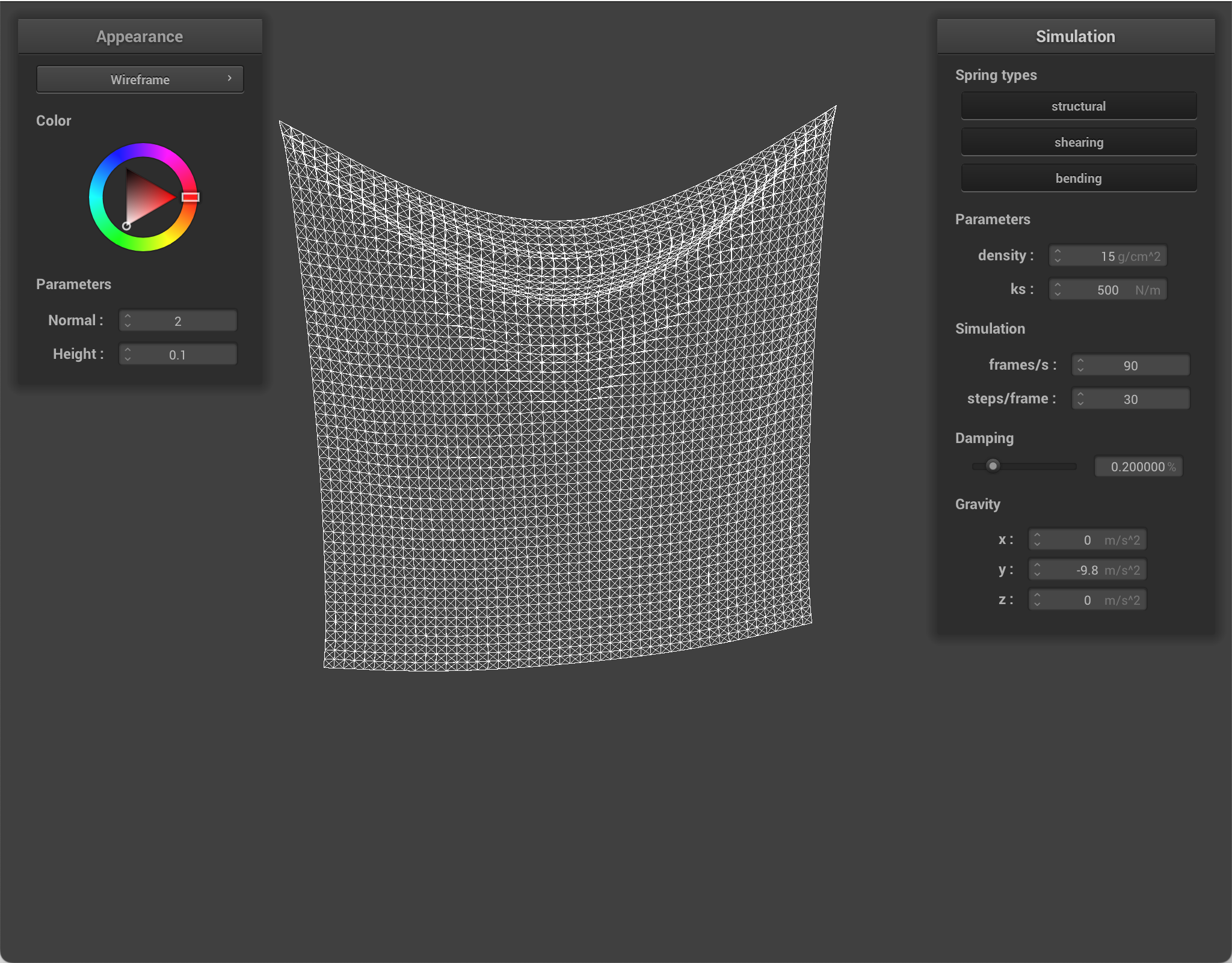
When I lower density, the cloth becomes stiffer/tighter. The higher density is, the saggier the cloth is. Lowering density reduces each point mass, so gravity contributes less force and the cloth sag less.
When I lower ks (spring stiffness), the cloth sags more. It falls slower, feels more flowy. Lowering ks makes the springs weaker, so the cloth stretches more and seems softer. Increasing k increases resistance.
When I increase damping, nothing seems to change with the final result. Damping means that there is less jitter/bouncing, so the oscillations of the springs die out faster. When running the simulation, the higher damping was, the slower the cloth fell and the longer it took to settle.
Here are simulations with different parameters changed.

|
|
|
|
|

|
|
|
|
Part 3: Handling collisions with other objects
I implemented collision with a sphere. I checked whether the point mass was inside the sphere. If so, I projected it to the sphere surface (the tangent point), computed a correction from its previous position, and updated its new position using the correction scaled by (1 - friction).
Here is an expample of sphere collision where different ks values are used. ks is basically spring stiffness. Since lower ks means softer cloth, when the ks is low, we can see that the cloth stretches more and wraps more smoothly around the sphere. However, when ks is higher, the cloth is stiffer, so it resists stretching and maintains a bit more of its shape over the sphere.
|
|
|
I also implemented collision with a plane. I checked whether the point mass crossed the plane between the last and current timestep. If it crossed, I computed the intersection between the line and plane (which is the tangent point), moved slightly above the plane using a small surface offset, and applied the same correction scaled by (1 - friction) from the previous position.
In simulation, I looped through every point mass and test collisions against every collision object ever timestep.
|
|
Part 4: Handling self-collisions
To implement self collisions, I first created a hash function. I split the 3D space around the cloth into small boxes (dimensions w * h * t), and then assigned each point to one of those boxes based on its position. The reason for partitioning this way is speed. Most point masses are far away from each other and will not collide, so there is no point in comparing all the points to each other. By grouping nearby point masses into the same box, I am only checking collisions among neighbors. After assigning a mass to a box, I convert that box location into a single unique hash key so that masses in the same region are stored together.
Then, I built a spatial map. At every simulation step, I rebuilt the hash table using the point masses' updated positions. I looped through all the point masses, computed the hash key for each, and inserted a pointer to that mass in the corresponding hash bucket.
Finally, I check self collision. One point mass at a time, I computed the hash key, looked up its position in the hash table, and iterated through the point masses stored there. For each, I measure the distance, and if it's overlapping, I included a small correction that pushes the current mass away. Then, I accumulated all of these individual corrections and then averaged them for the final displacement (and scaled them by number of simulation steps). This prevents the cloth from intersecting with itself!
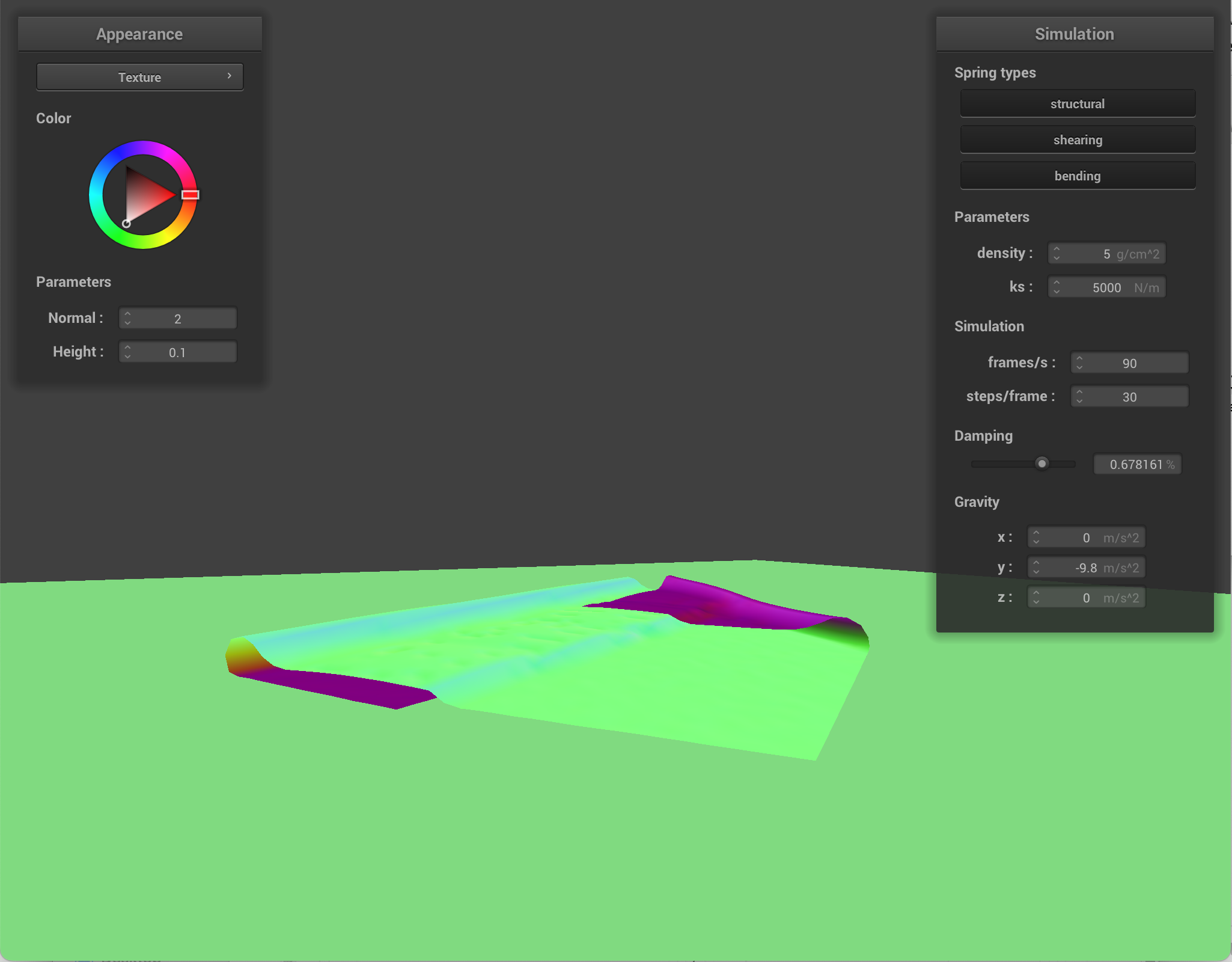
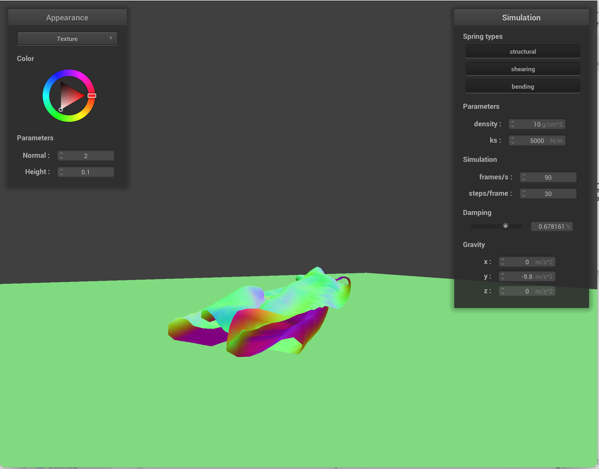
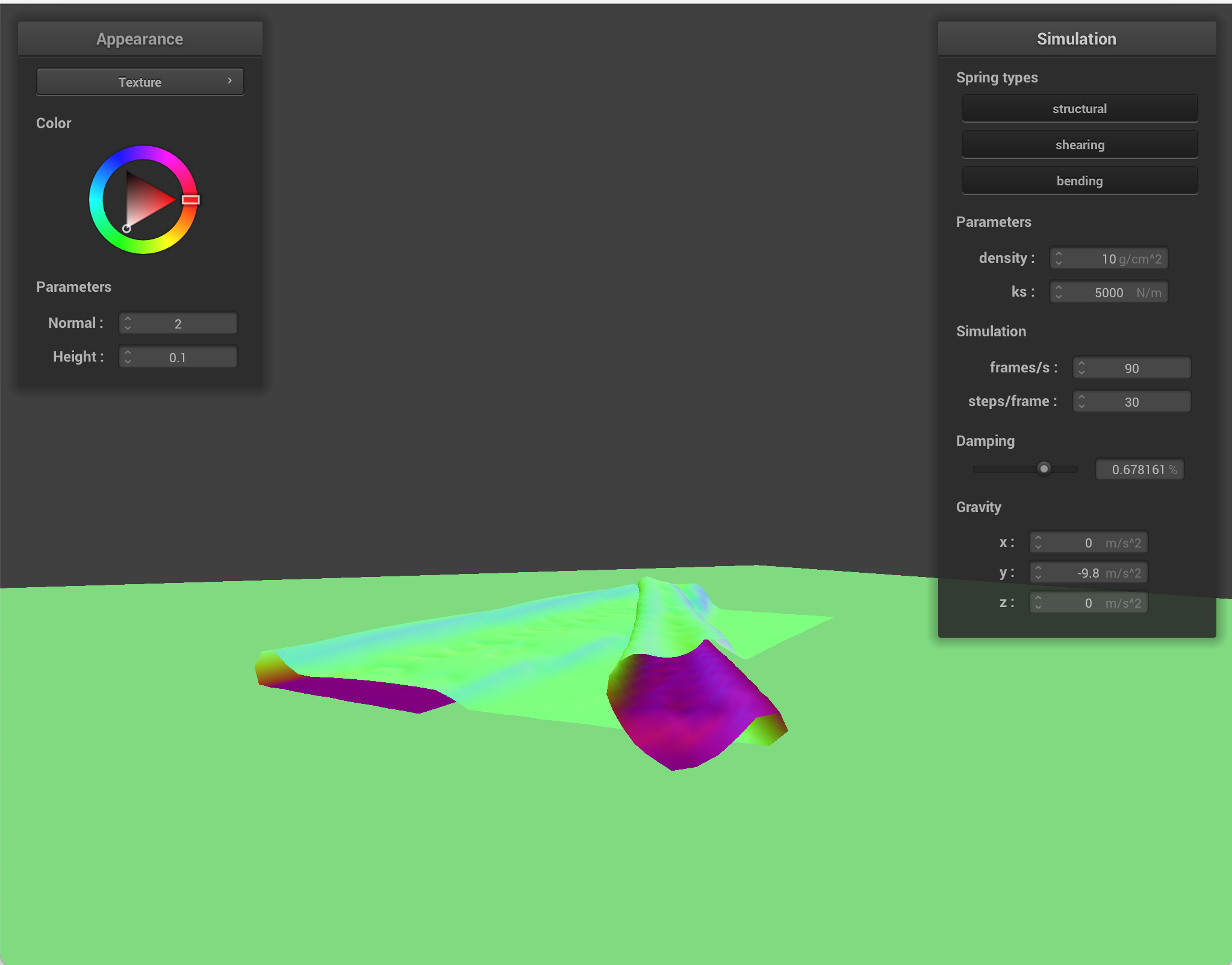
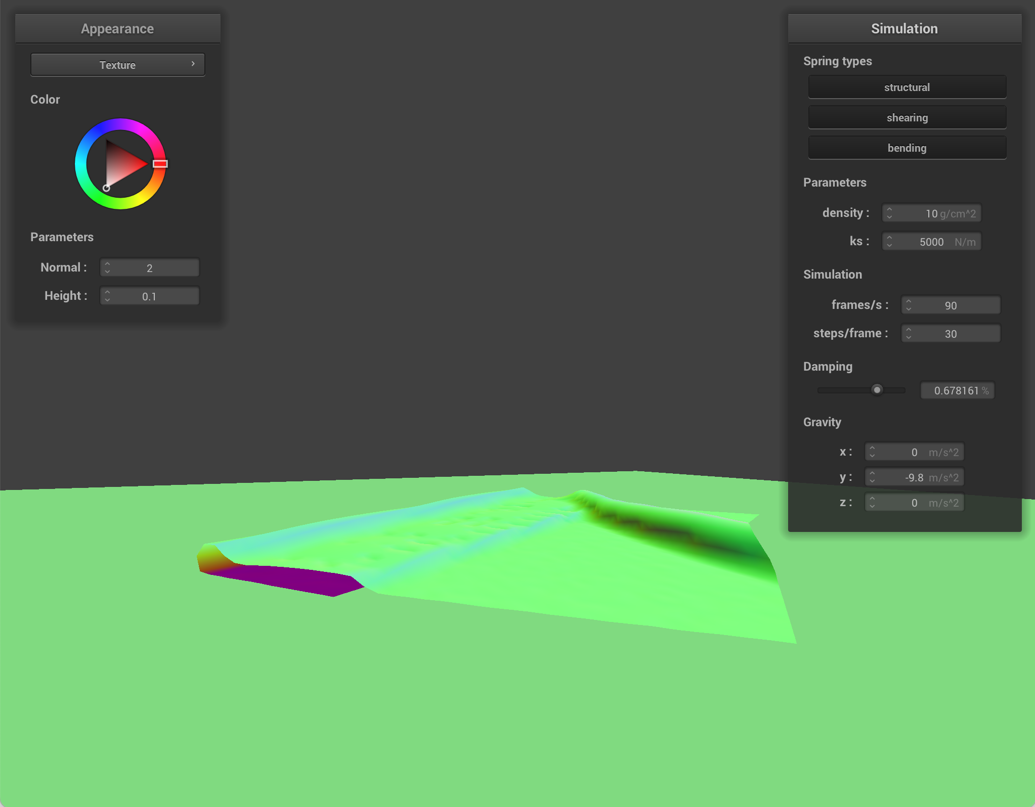
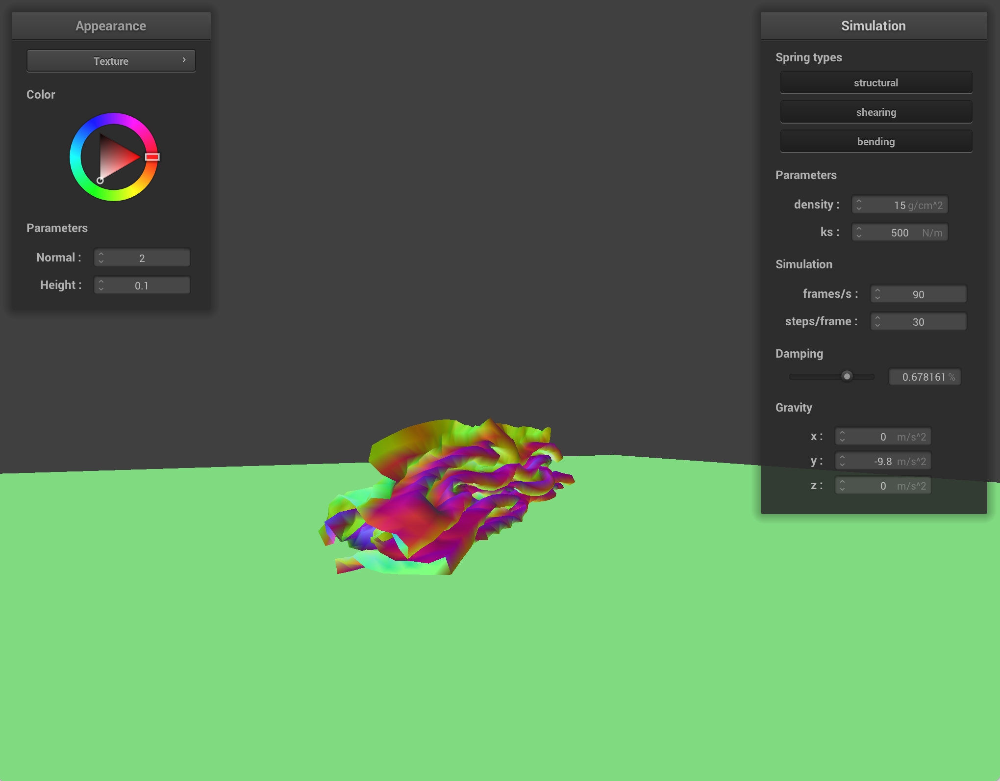
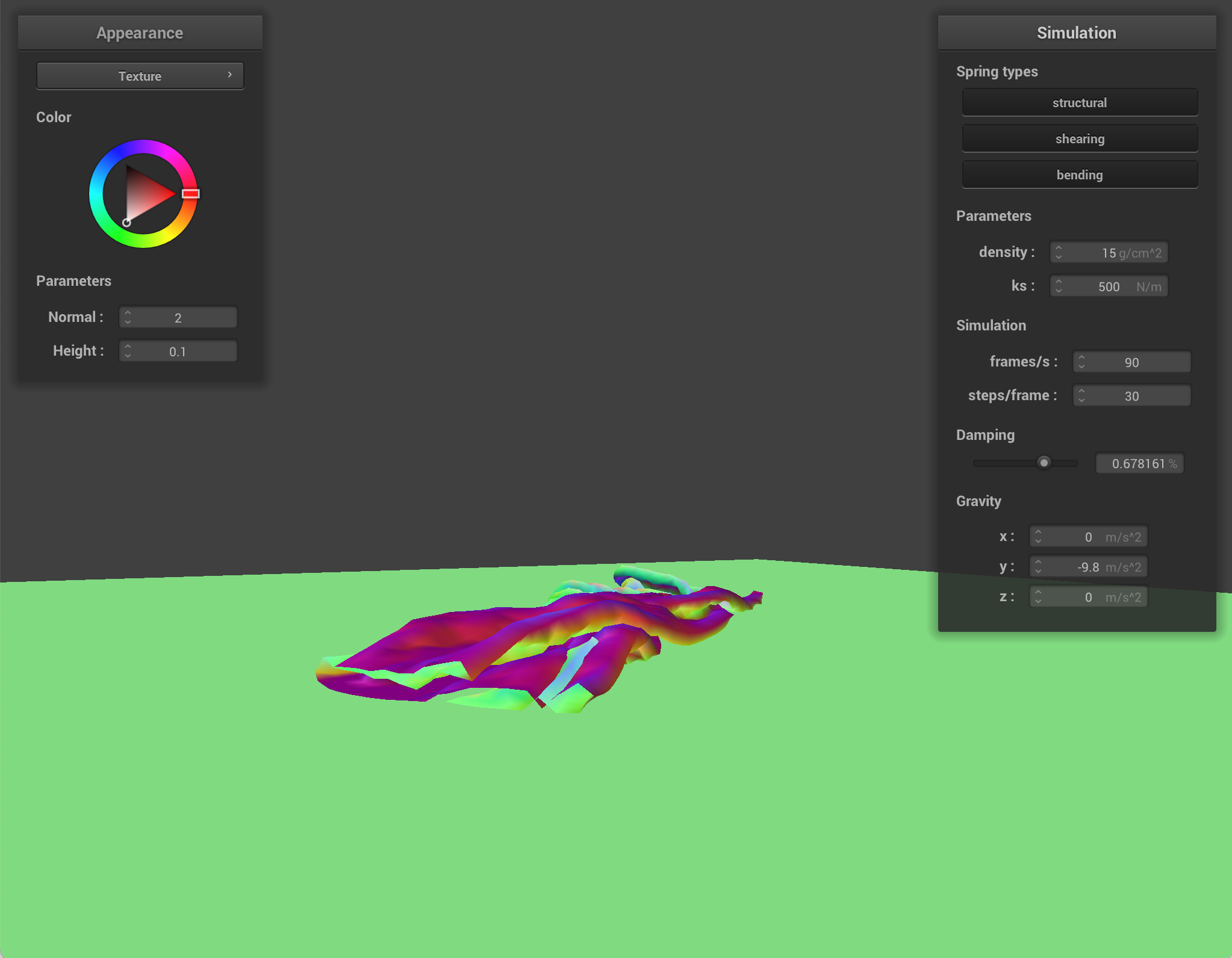
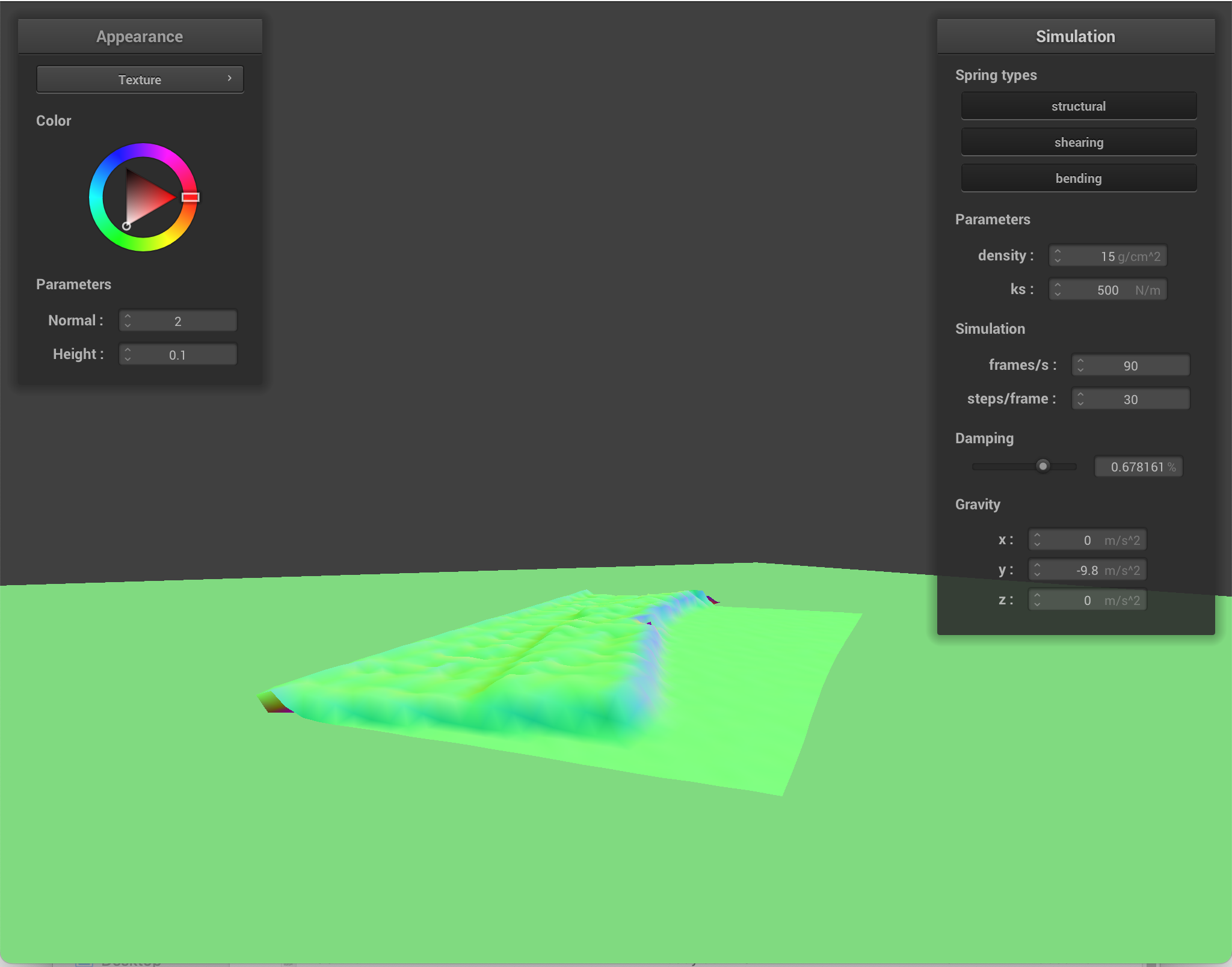
Differences between changing parameters
When I change density, the cloth's mass changes. How heavy each point mass is changes, which affects how strongly the cloth compresses into itself. With lower density, the cloth is lighter, so folds form more gently, and self-collision has milder effects. With higher density, the cloth pushes layers together more forcefully, so there is more self collision.
When I modify ks, how stiff the springs are changes, which changes how easily the cloth deforms into places where there is self contact. With lower ks, the cloth is softer and bends/folds more easily, so it has many deep wrinkles and more self collision interactions. With higher ks, the cloth resists deformation, so it forms smoother folds and has less self collision because layers do not collapse into each other as much.
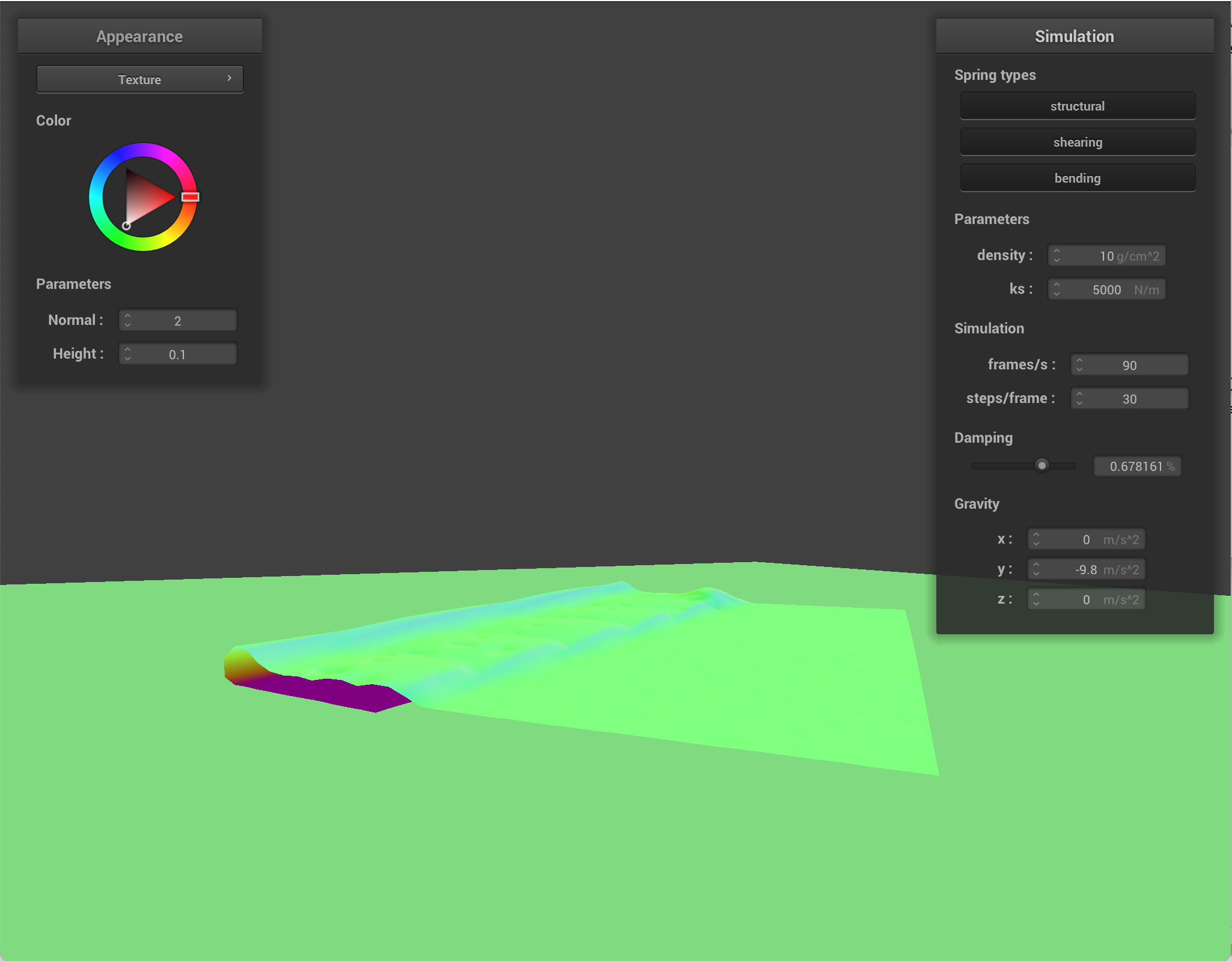
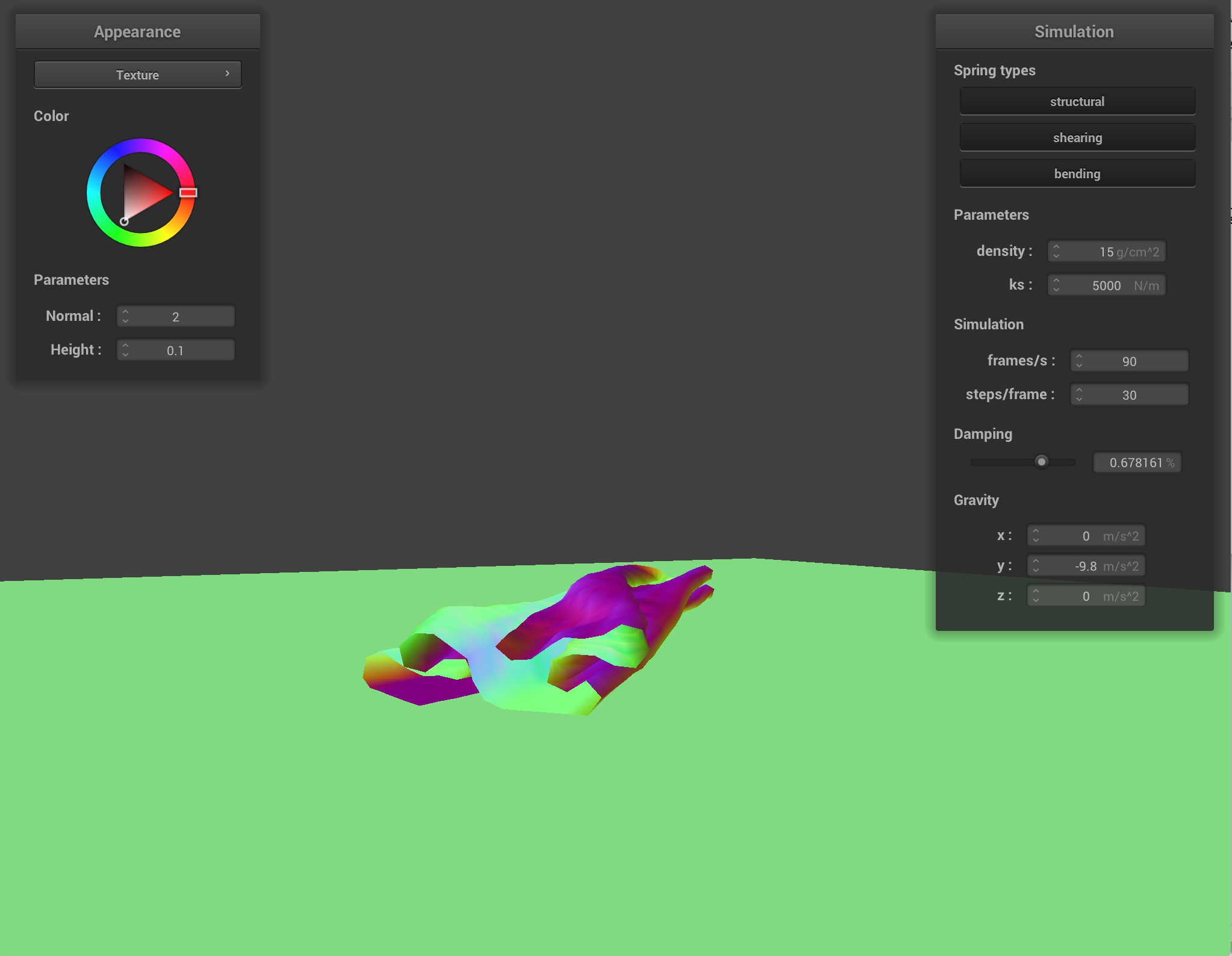
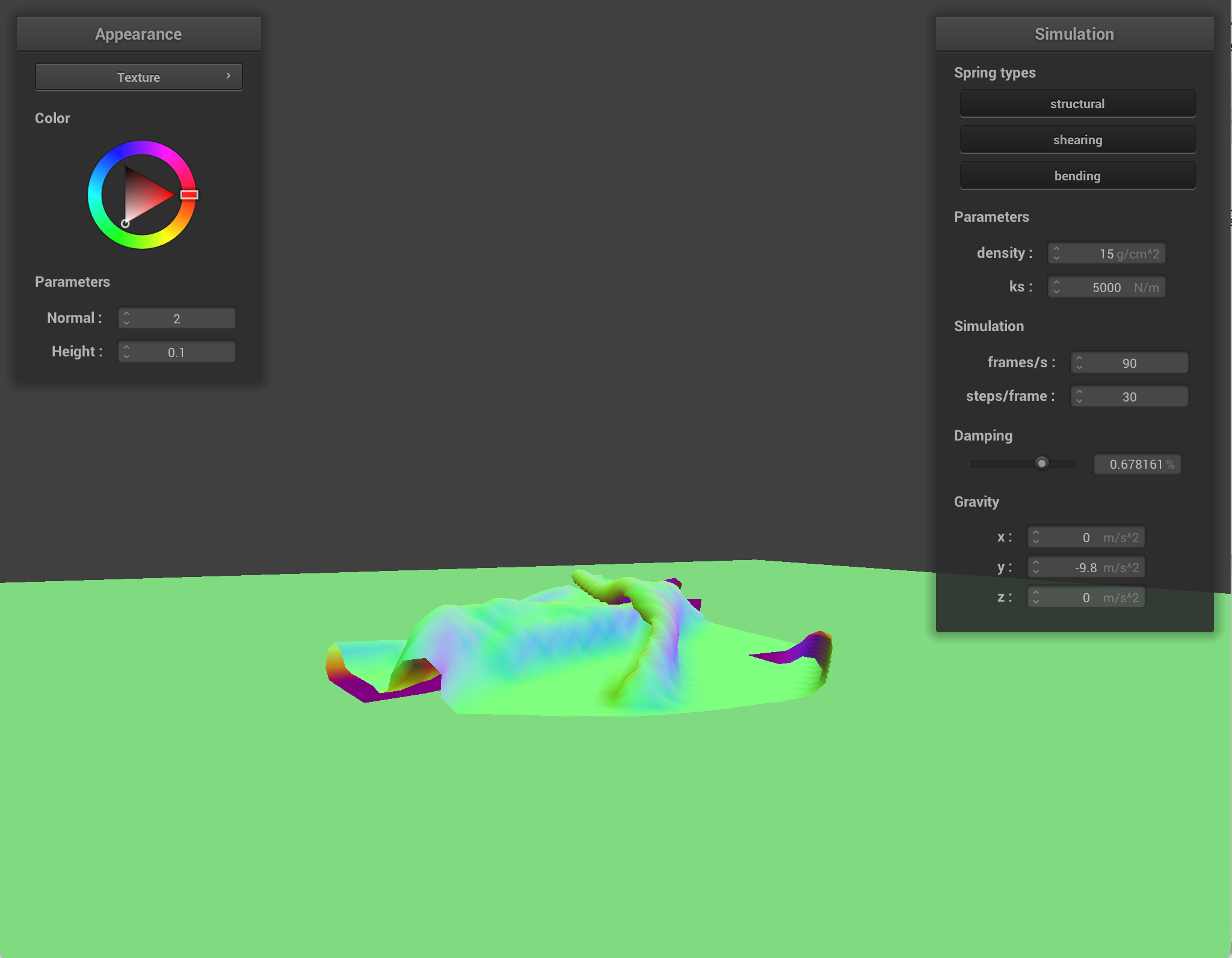
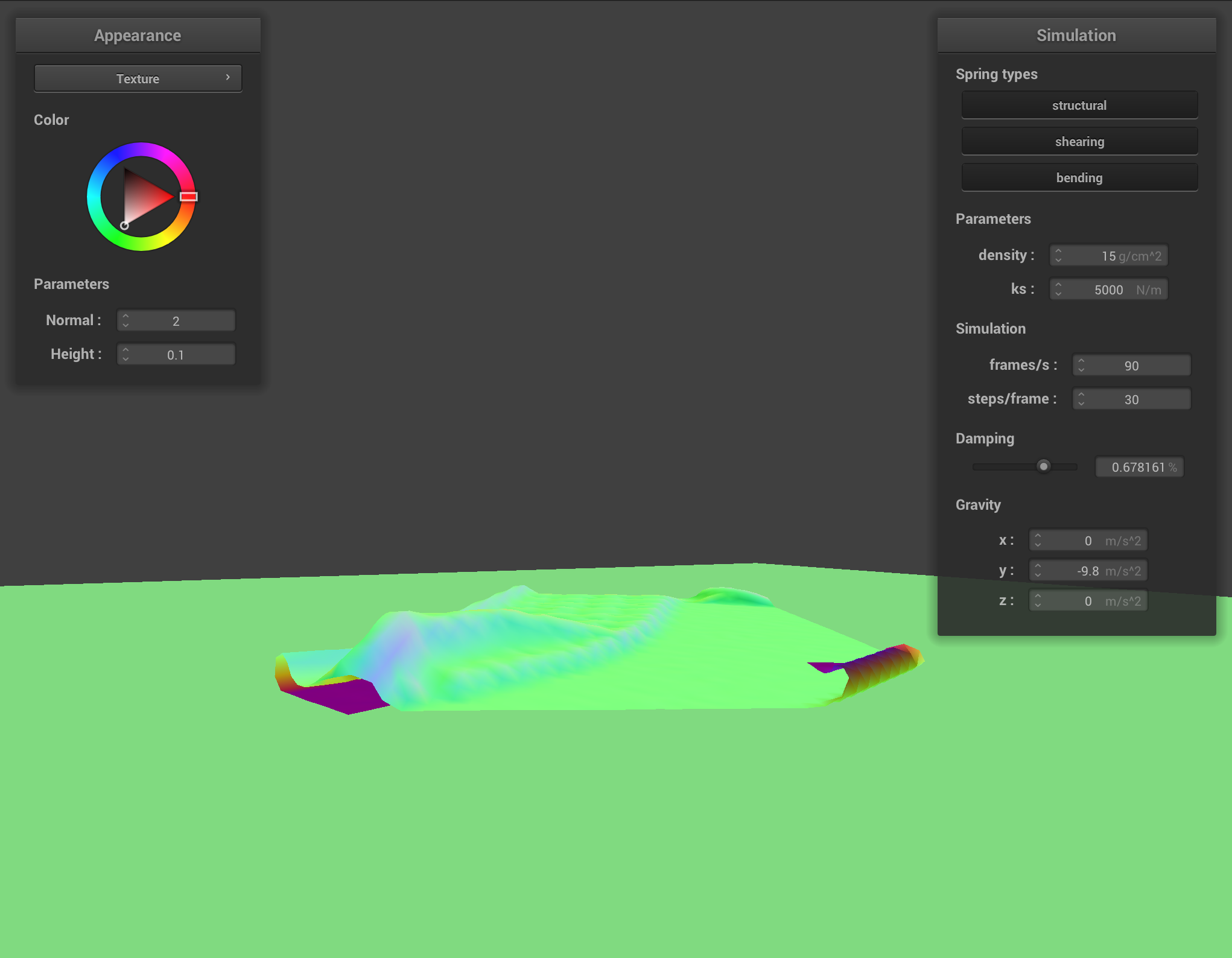
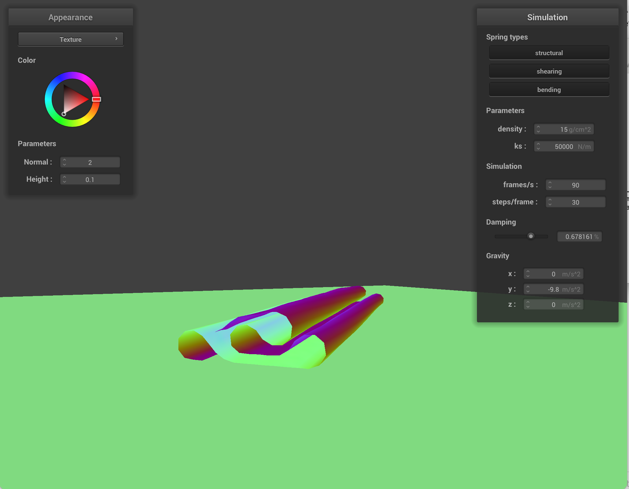
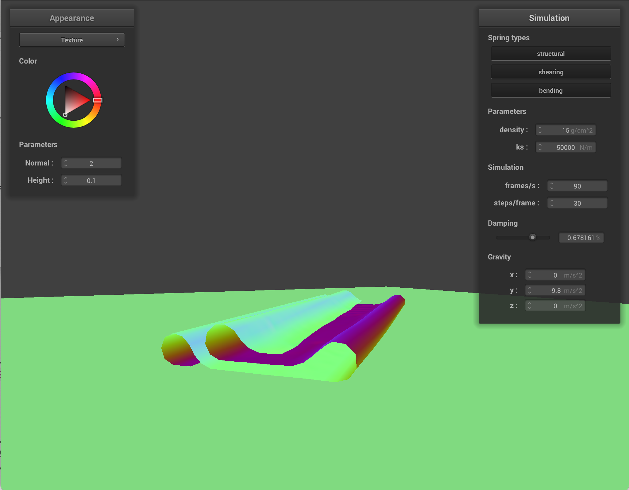
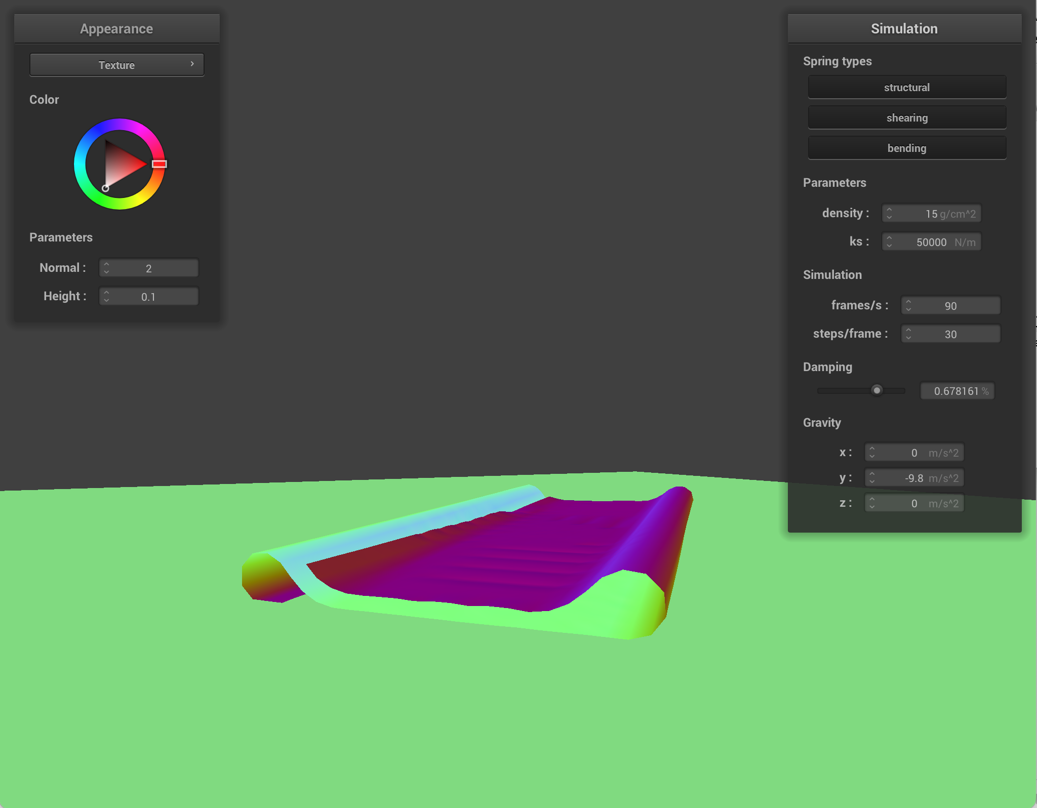
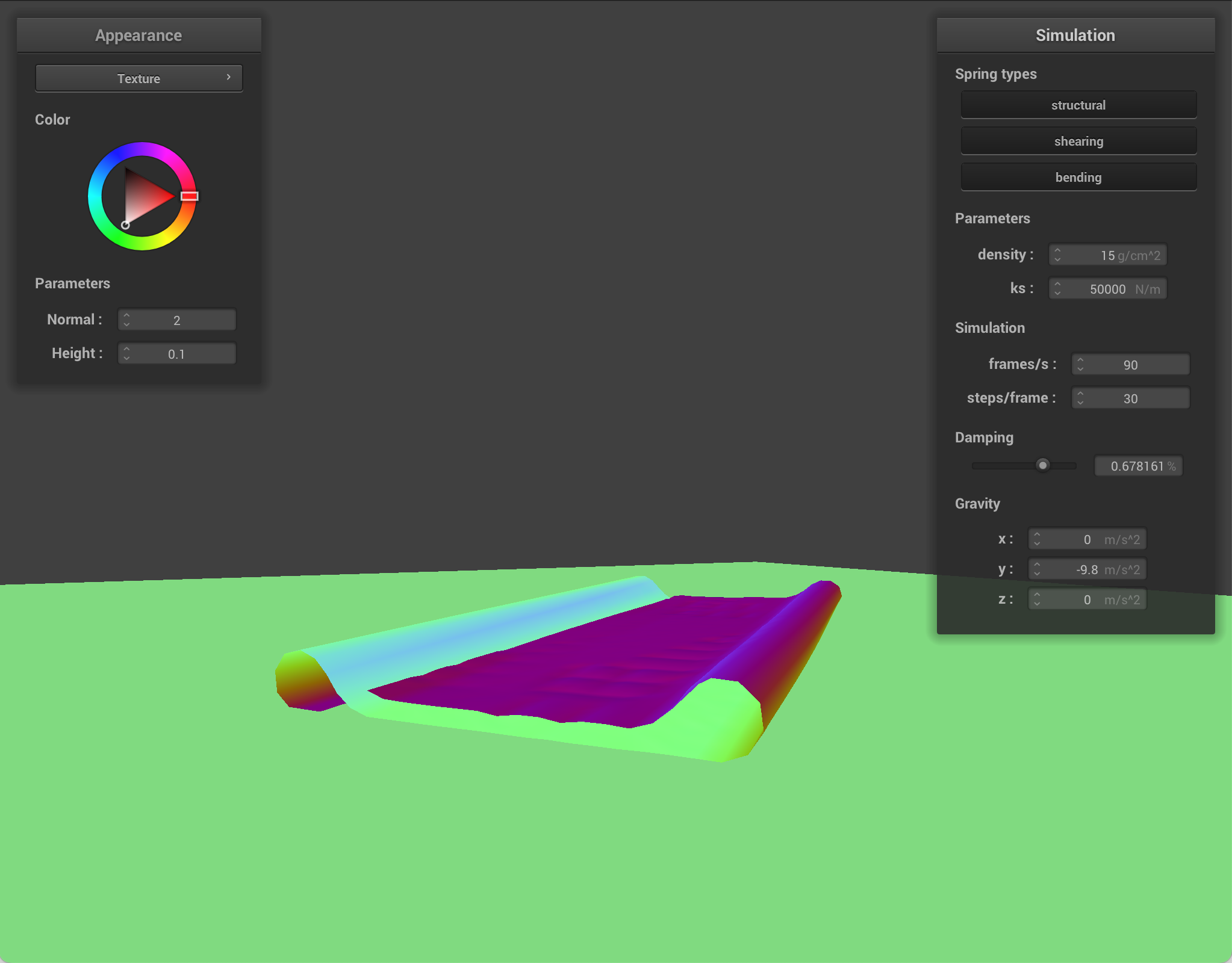
Here are simulations with different parameters changed at different steps in time.
Modified density
|
|
|
|
|
|
|
|
|
|
|
|
Modified ks
|
|

|
|
|
|
|
|
|
|
|
|
Part 5: Shaders
A shader program is a small program that runs on the GPU. It tells the GPU how to turn mesh data (like positions and normals) into colored pixels on the screen. A vertex shader and fragment shader are paired: the vertex shader runs once per vertex and the fragment shader runs many times per triangle. The vertex shader transforms each vertex and can pass interpolated values to the fragment shader. The GPU rasterizes triangles and linearly interpolates across the surface. The fragment shader then runs at each fragment with those interpolated values. Lighting and materials are often done in the fragment shader: you use the interpolated position and normal to compute how much light hits that point, and then output a color. The vertex shader mainly does geometry and prepares correct inputs, and the fragment shader deals with appearance.
Blinn Phong
Blinn Phong approximates how a surface looks under light by adding three parts:
- Ambient: a flat baseline so shadows are not pure black. It does not depend on where the light or camera is.
- Diffuse: light that bounces off roughly equally in many directions. It depends on how directly the surface faces the light.
- Specular: bright highlights.
For Blinn Phong, there were a few parameters I could customize in the code.
- ka: This is the ambient coefficient. It represents how strongly the surface picks up the ambient term. It scales the fill light that doesn't depend on the point light direction. Higher ka means that dark areas/unlit sides stay brighter. The whole object looks flatter and more evenly lit. Lower ka means that shadows/unlit areas go darker, and there is more contrast with directional diffuse/specular from the point light.
- kd: This is the diffuse coefficient. It represents how much incoming light is scattered diffusely. It is the base color strength of the diffuse. A higher kd means the lit parts of the surface look brighter and more saturated in that color. Lower kd means the diffuse contribution is dimmer.
- ks: This is the specular coefficient. It represents how strong the shiny highlight is (it's the Blinn Phong specular term). Higher ks means it's brighter and the surface looks glossier. Lower ks means that highlights are weaker. The surface looks more matte.
- Ia: This is the ambient light intensity/color. It models indirect/fill light. Higher Ia means that shadowy regions are overall lighter. Lower Ia means that shadows are deeper and there is more reliance on the point light for visibility.
- p: This is the sharpness of the specular. Higher p means the highlight is sharper, and it looks more metallic. Lower p means the highlight is broader and softer.
|

|
|
|
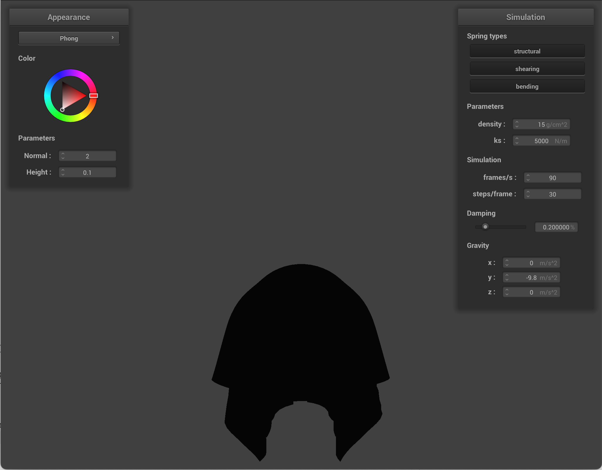
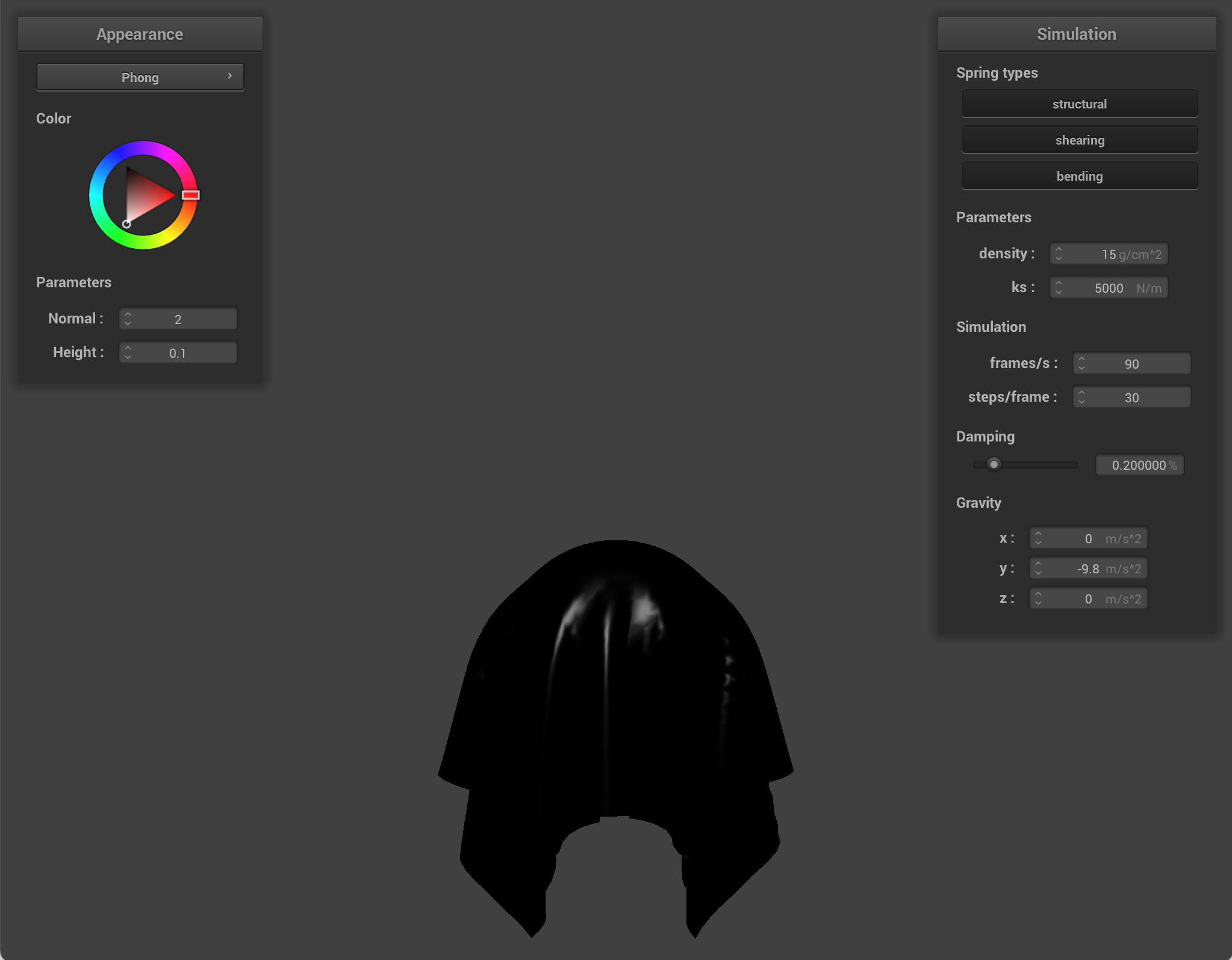
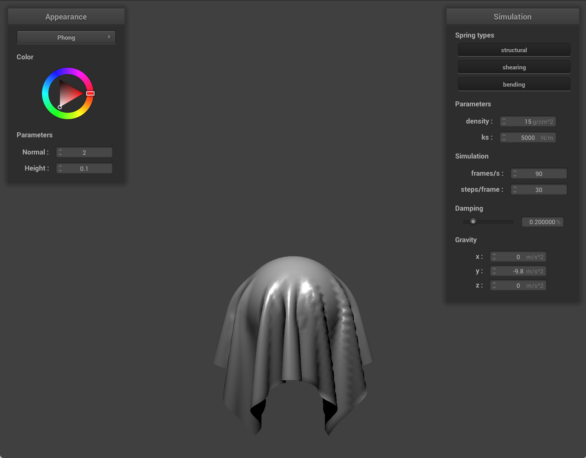
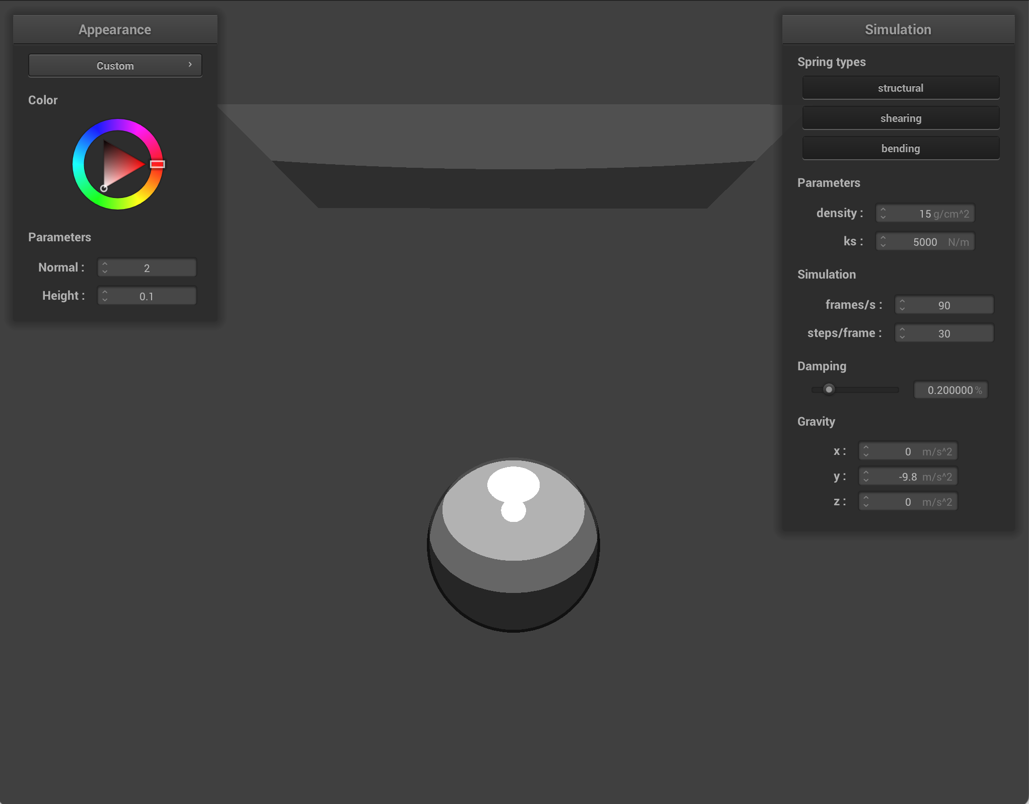
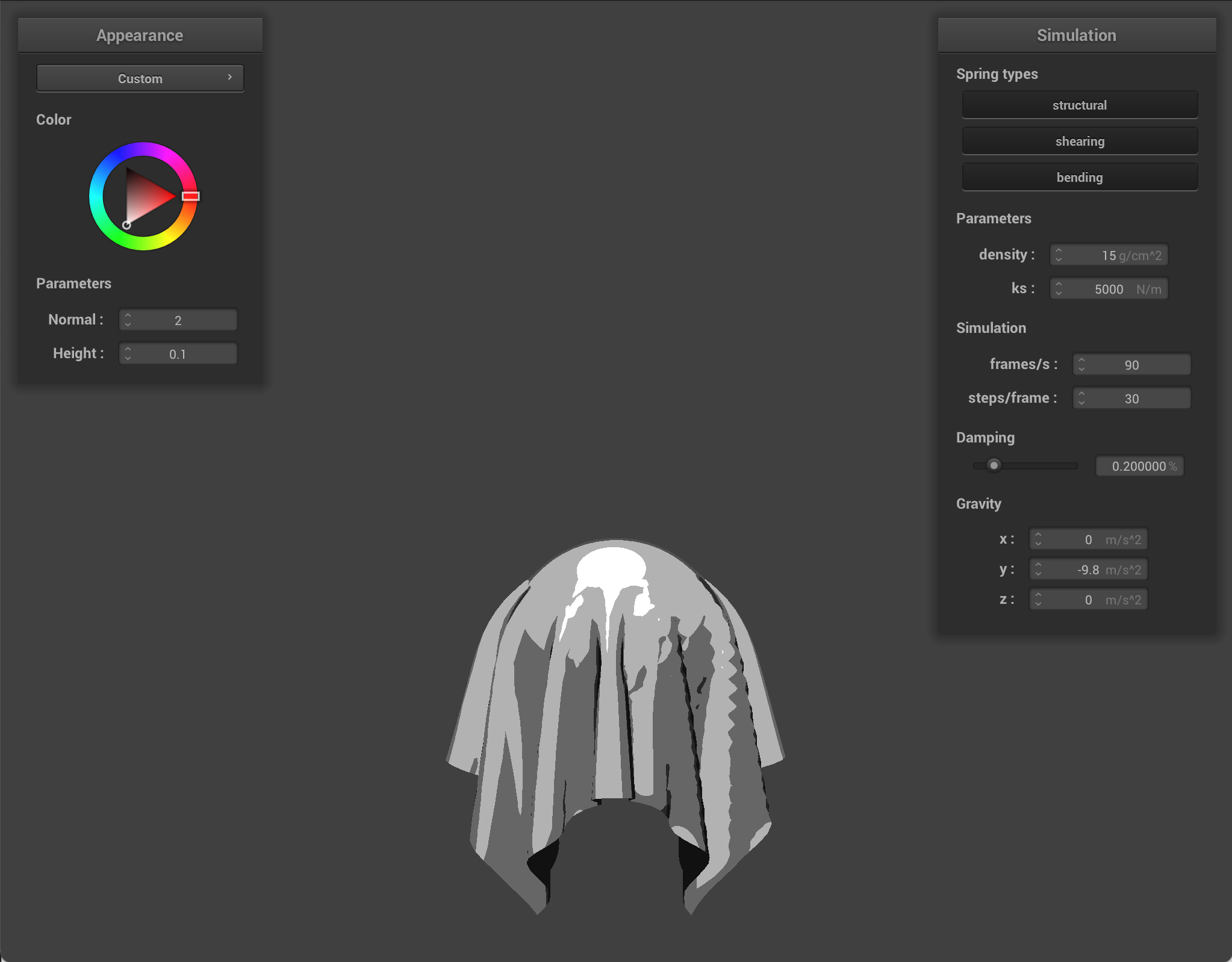
Texture mapping shader
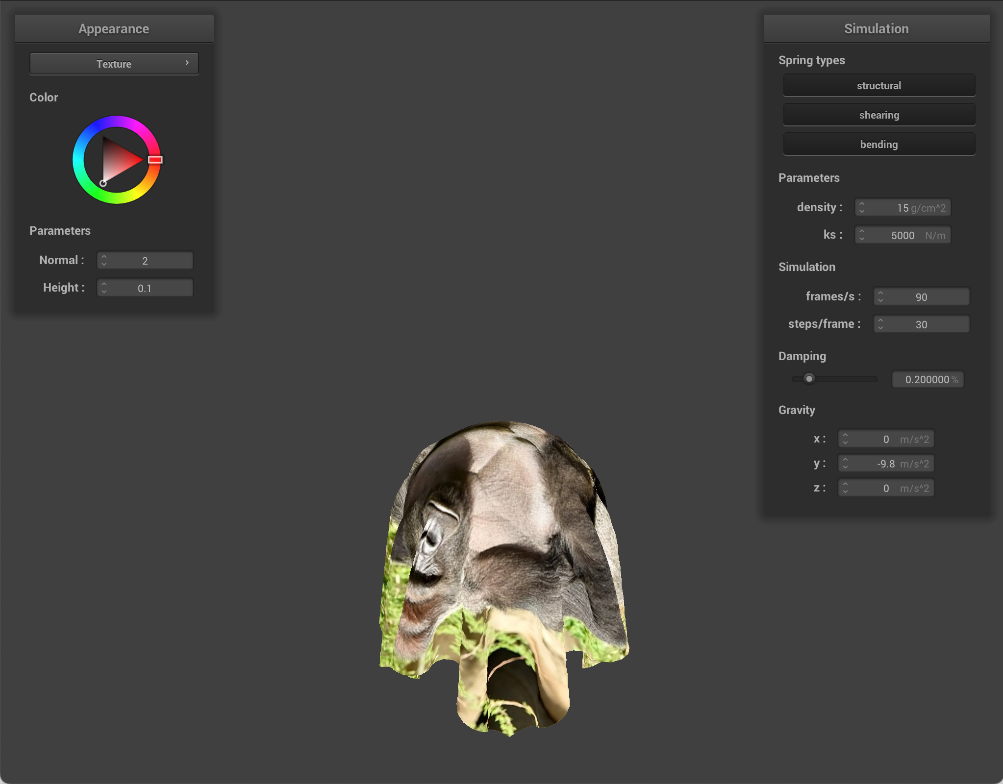
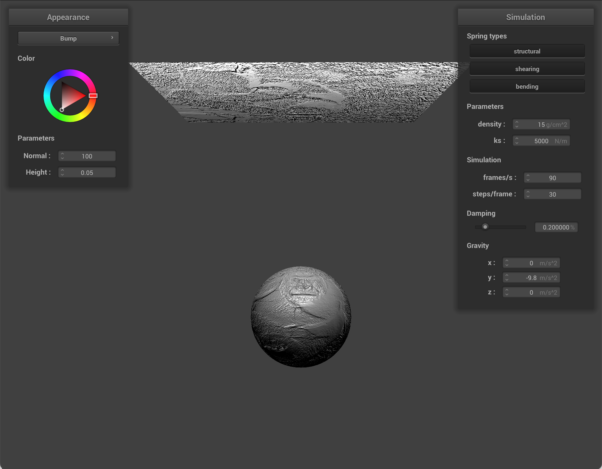
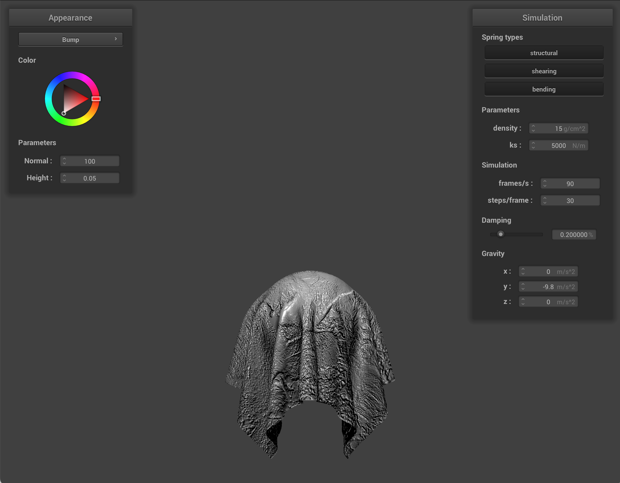
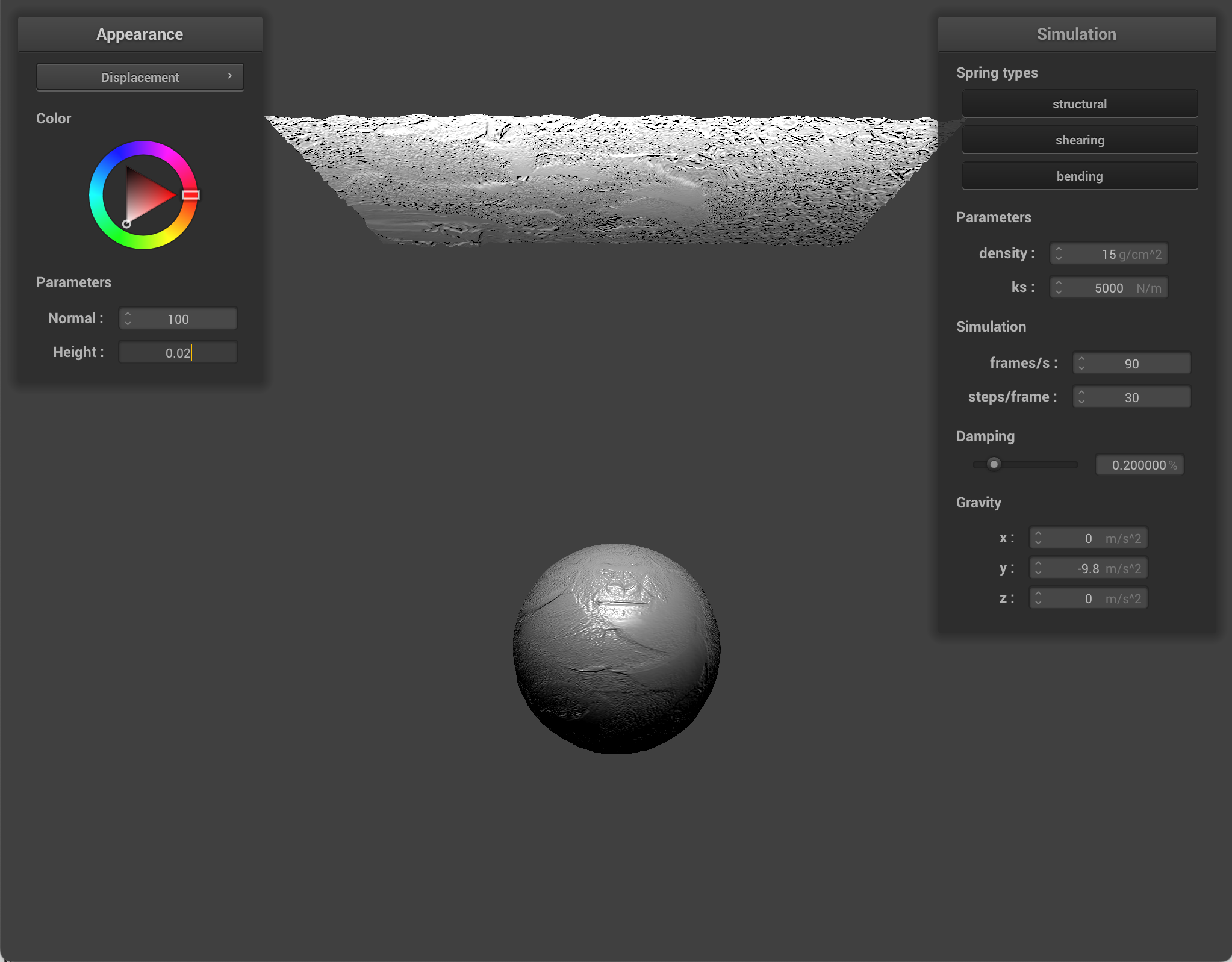
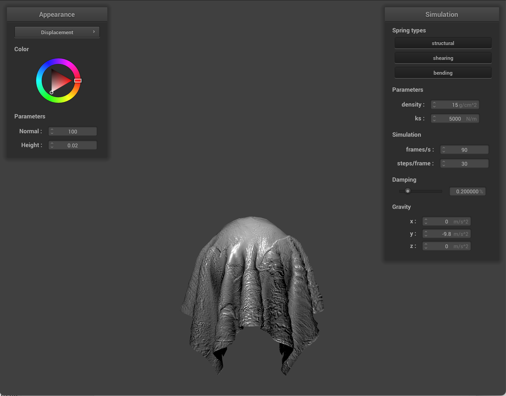
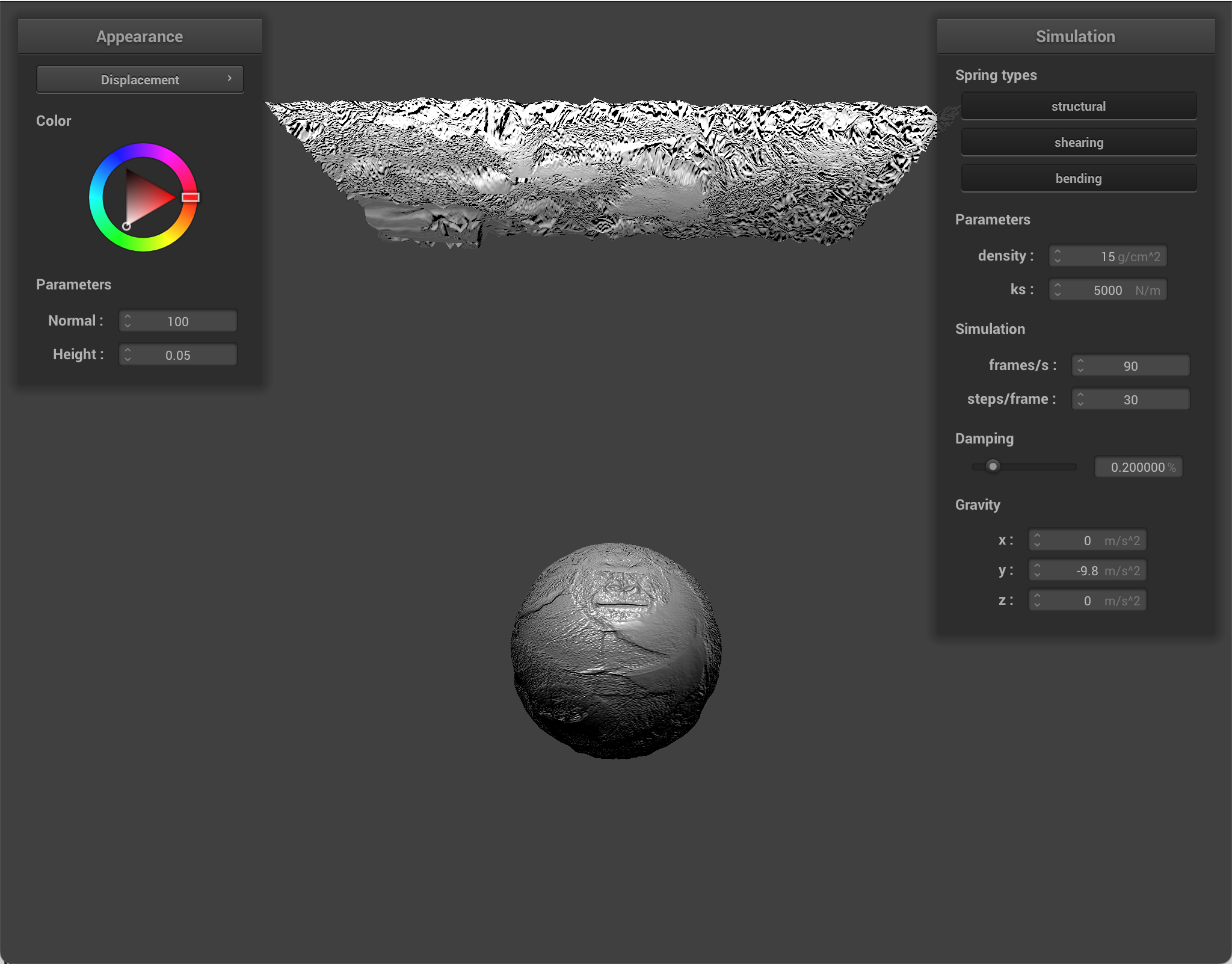
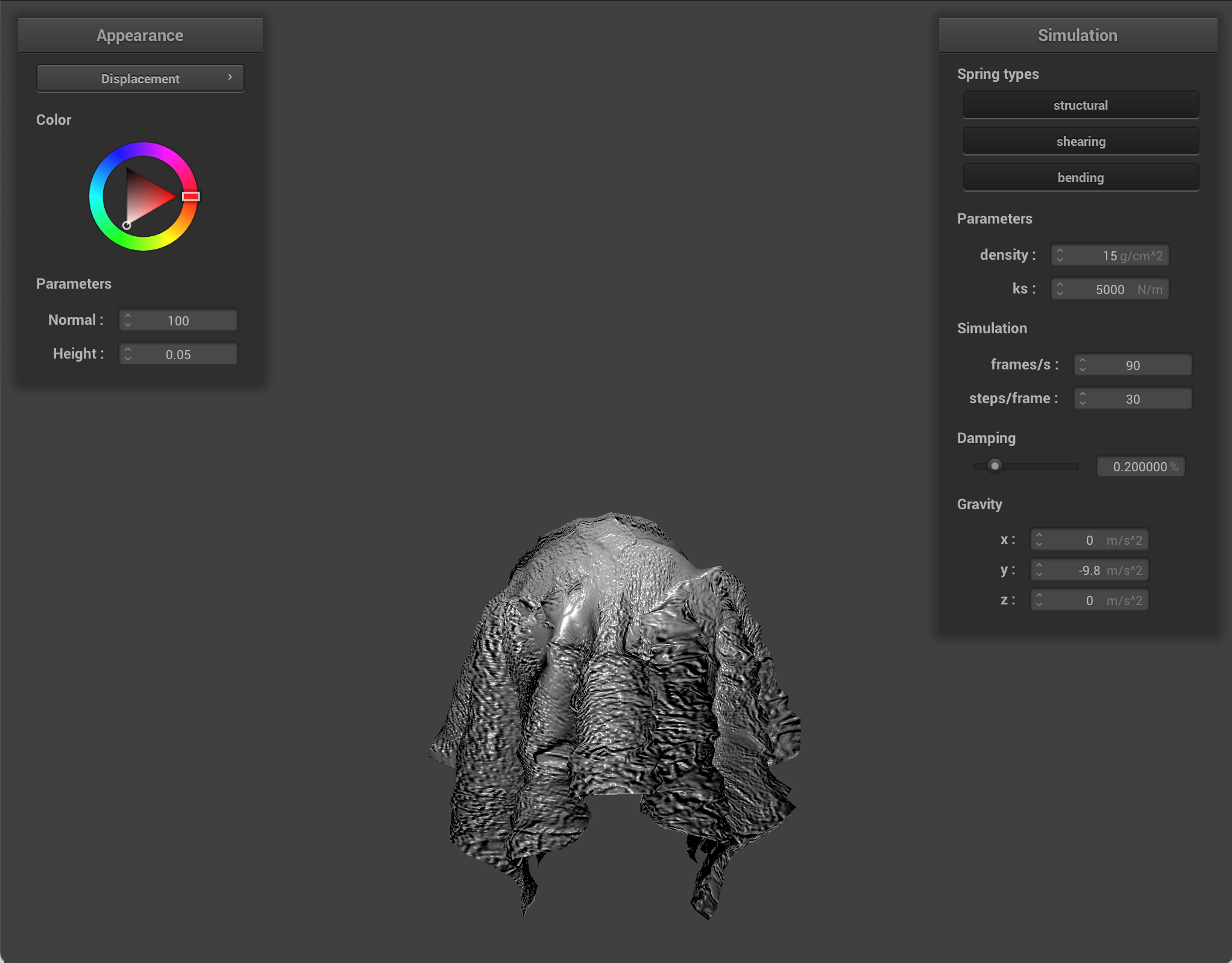
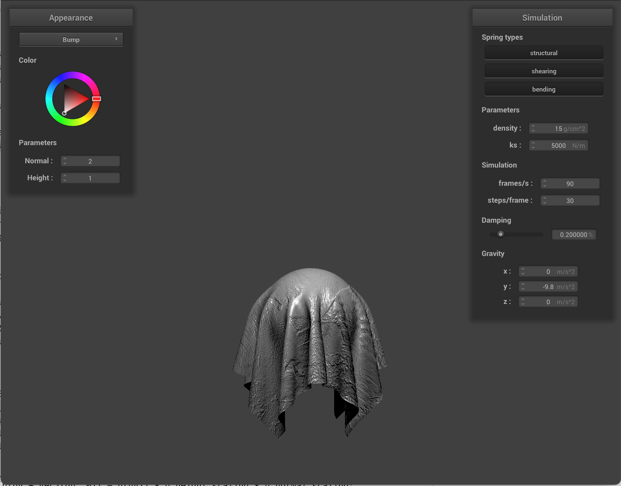
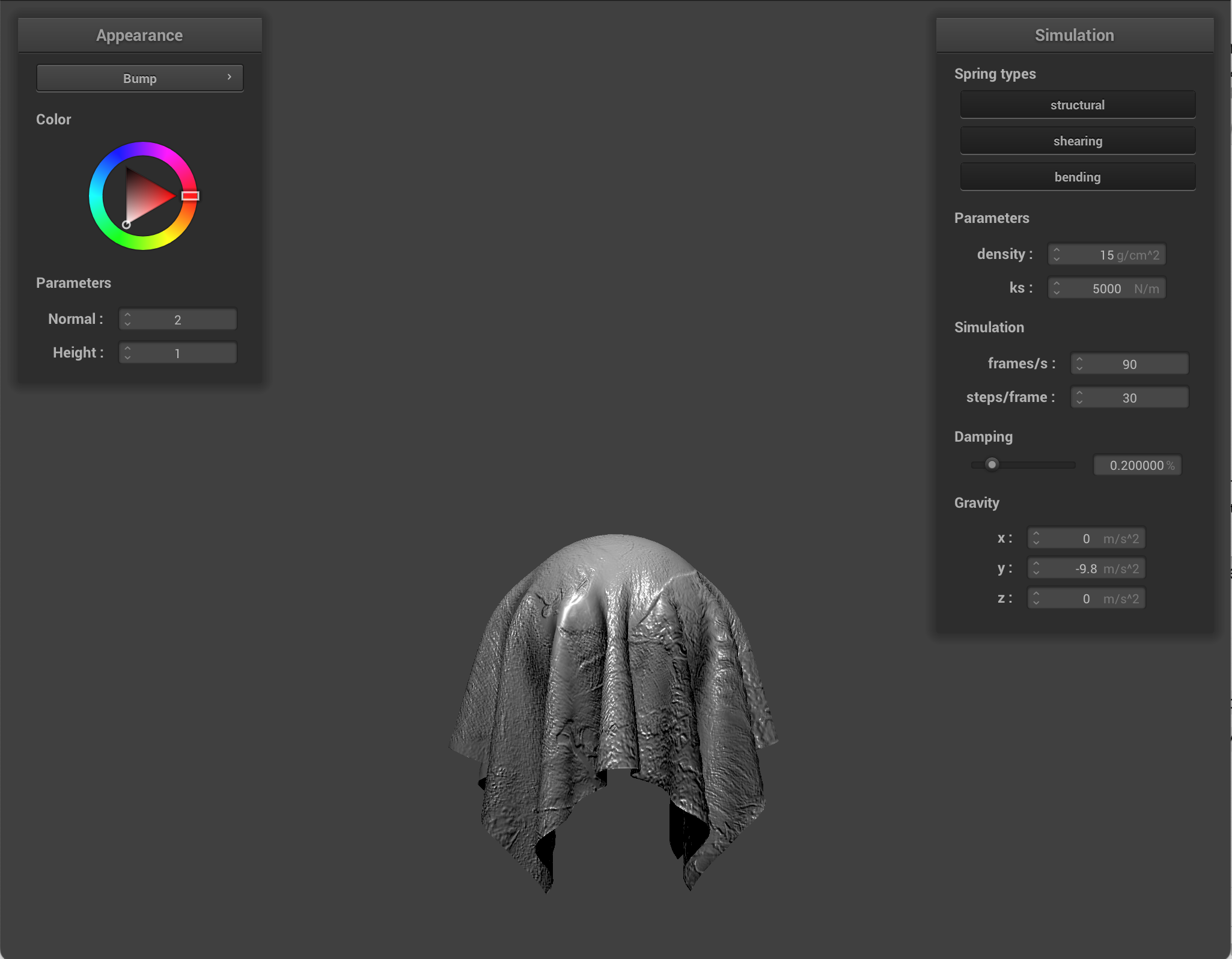
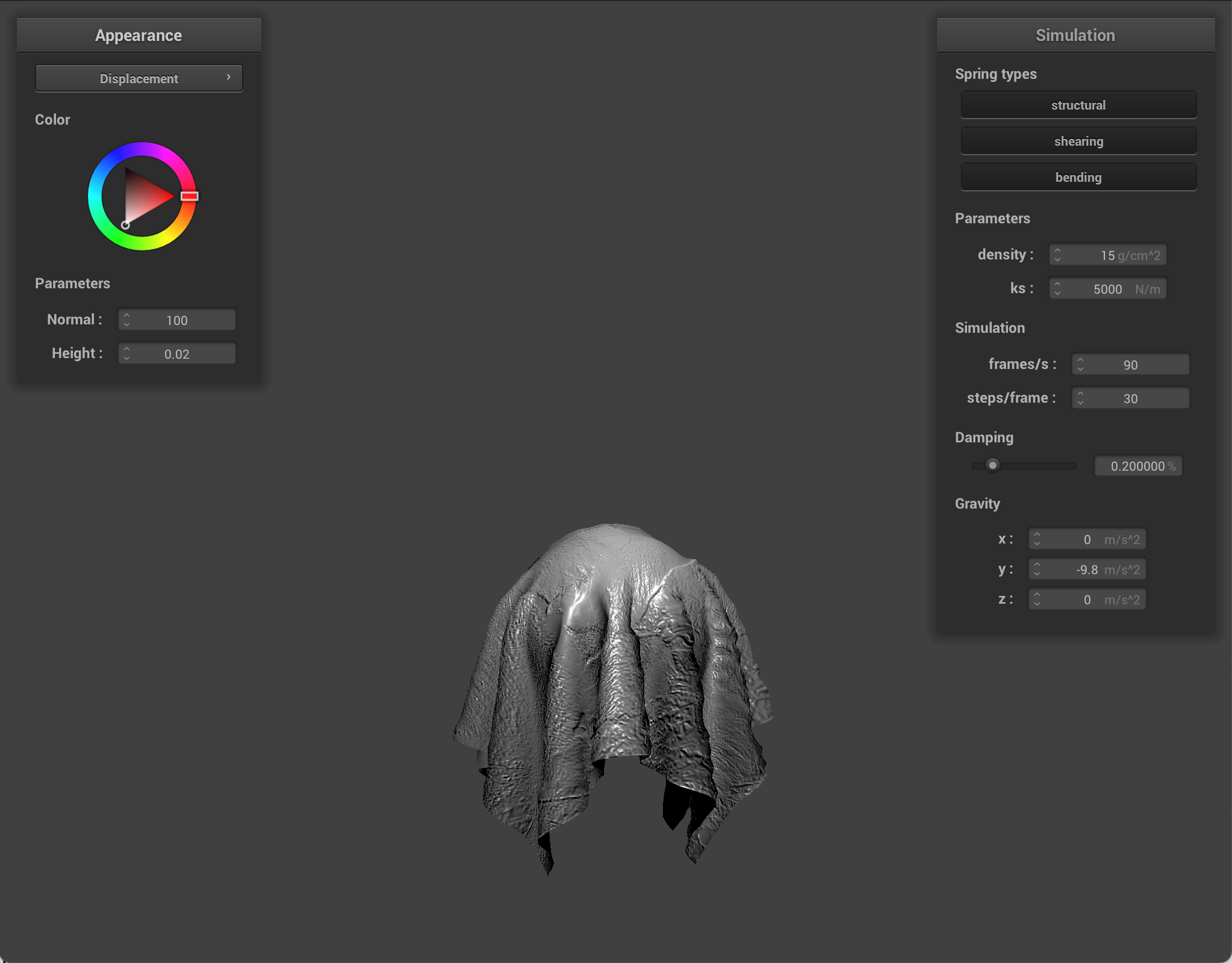
Bump mapping and displacement mapping
For bump mapping, I treated one texture as a height map and got local heights in u and v directions. I then built a normal in tangent space, and transformed it into world space using a TBN matrix (using the formula from the spec). Finally, I used this displaced normal in my Blinn Phong lighting computation, which created the illusion of surface variations/details.
For displacement mapping, I also used a height map, but I applied it in the vertex shader to directly effect the geometry. For each vertex I displaced the original vertex via a height scaling factor (via sampling), and used that to transform the world position, so the mesh shape and silhouette actually change.
Bump mapping changes only lighting normals, while displacement mapping modifies the actual vertex positions. If you look at the simulated images, you can see that bump mapping only changes the visible detail via lighting and normals. However, displacement has a more pronounced effect on texture. Modifying the height parameter makes the difference more stark.
|
|
|
|
|
|
Using different sphere coarseness:
When comparing bump and displacement shaders on a coarse sphere (16) vs a dense sphere (128), what I noticed was how each shader depended on mesh resolution. Bump mapping only changed the shading normals, so both looked pretty similar (coarse vs dense). However, displacement mapping modified actual vertex positions. On a coarser sphere, displaced geometry looked smoother and blockier. On the denser sphere, there were more vertices available to move, so there was more geometric detail.
|
|
|

|
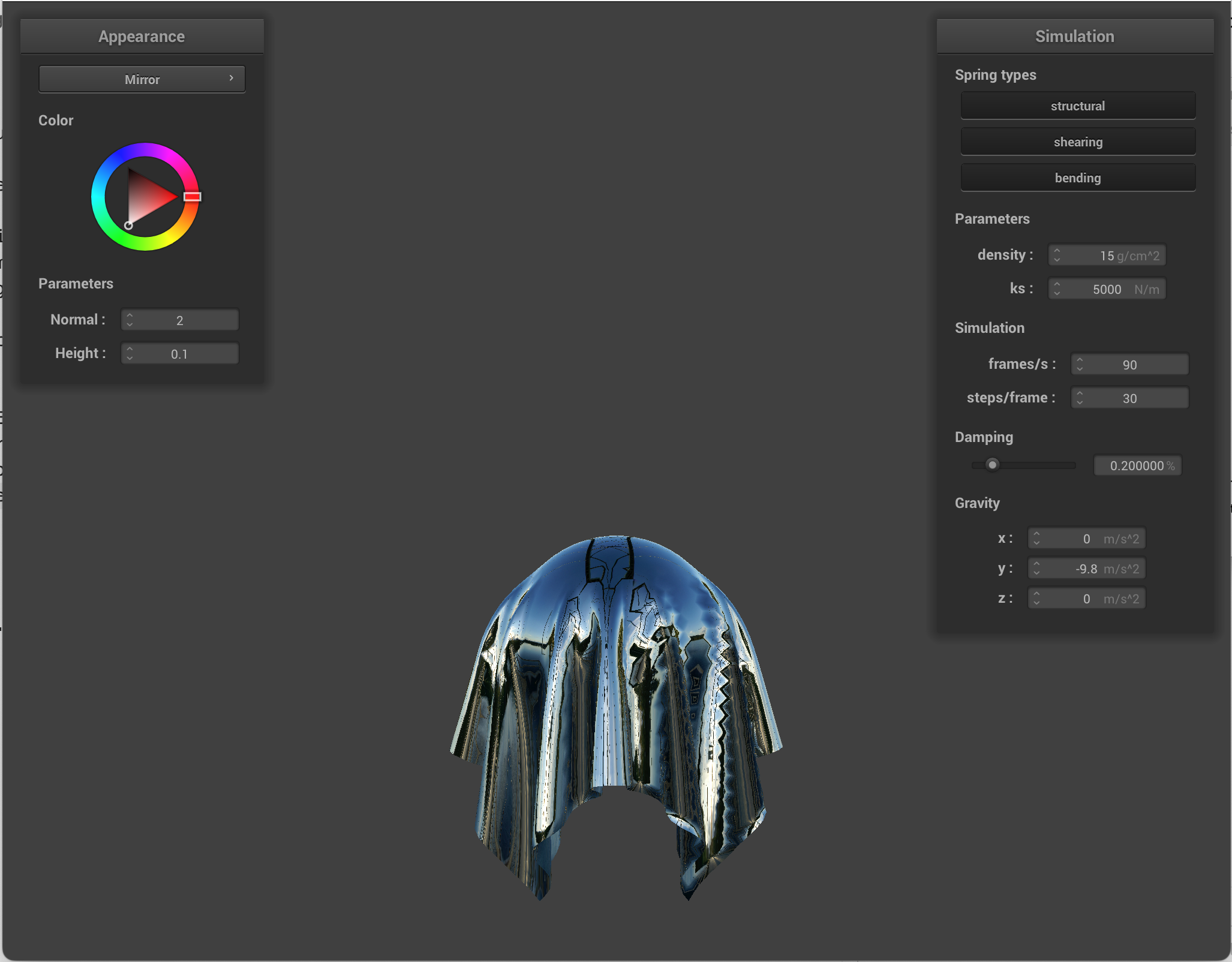
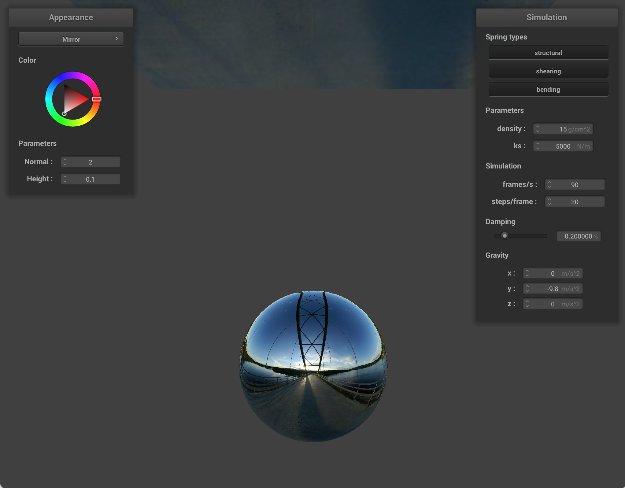
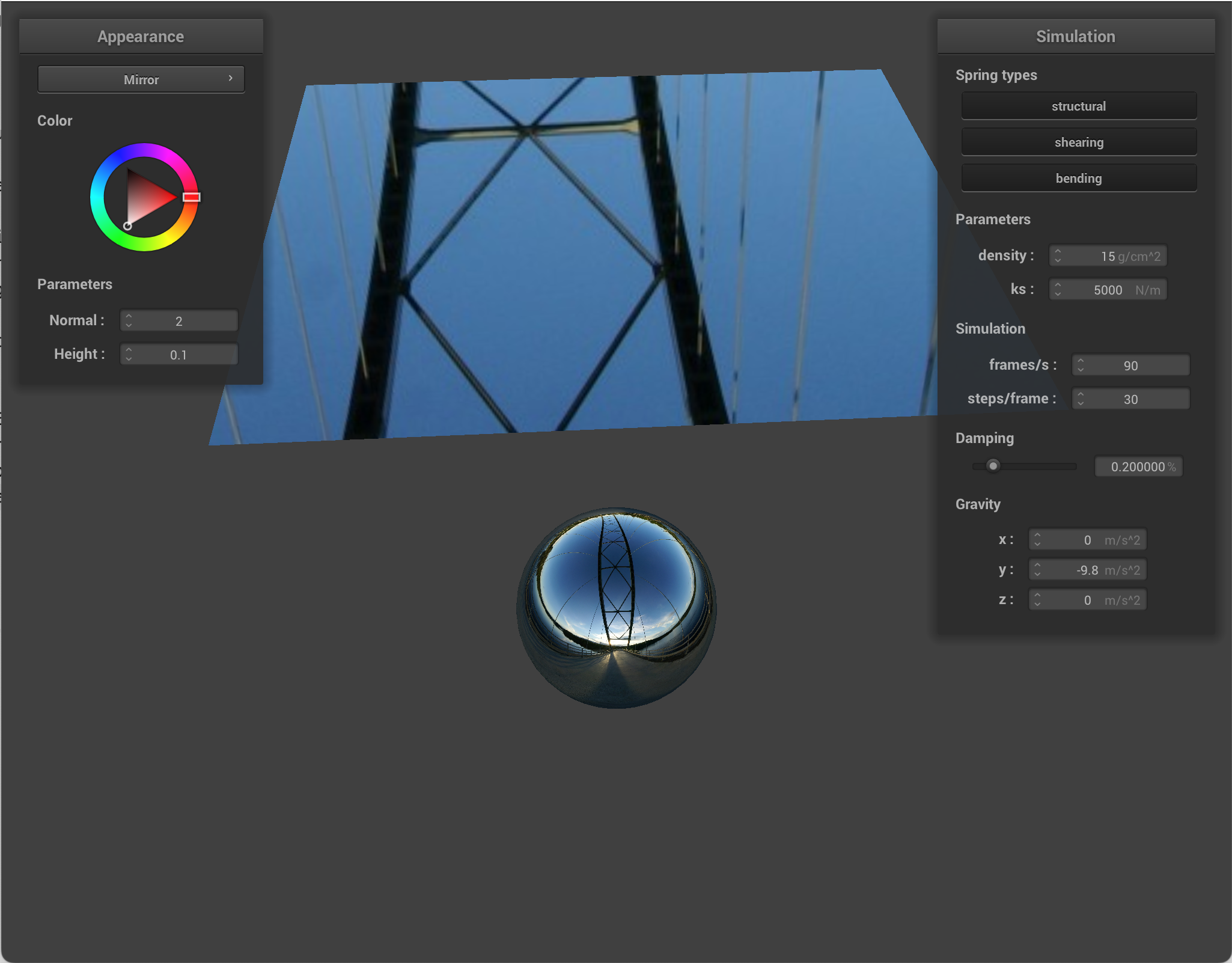
Environment-mapped reflections
I implemented reflective shading by treating each fragment like a specular reflector and sampling a cubemap in the reflected direction. At each fragment, I computed the outgoing view direction, and reflected that across the interpolated surface normal to get the reflected incoming direction. Then I approximated radiance by sampling the environment cubemap, which became the final output color.
|
|
|
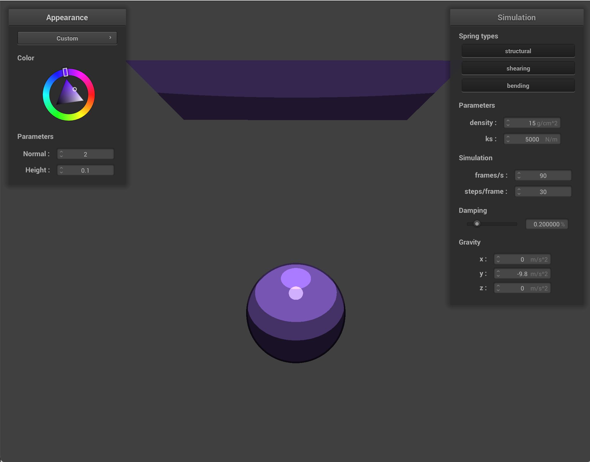
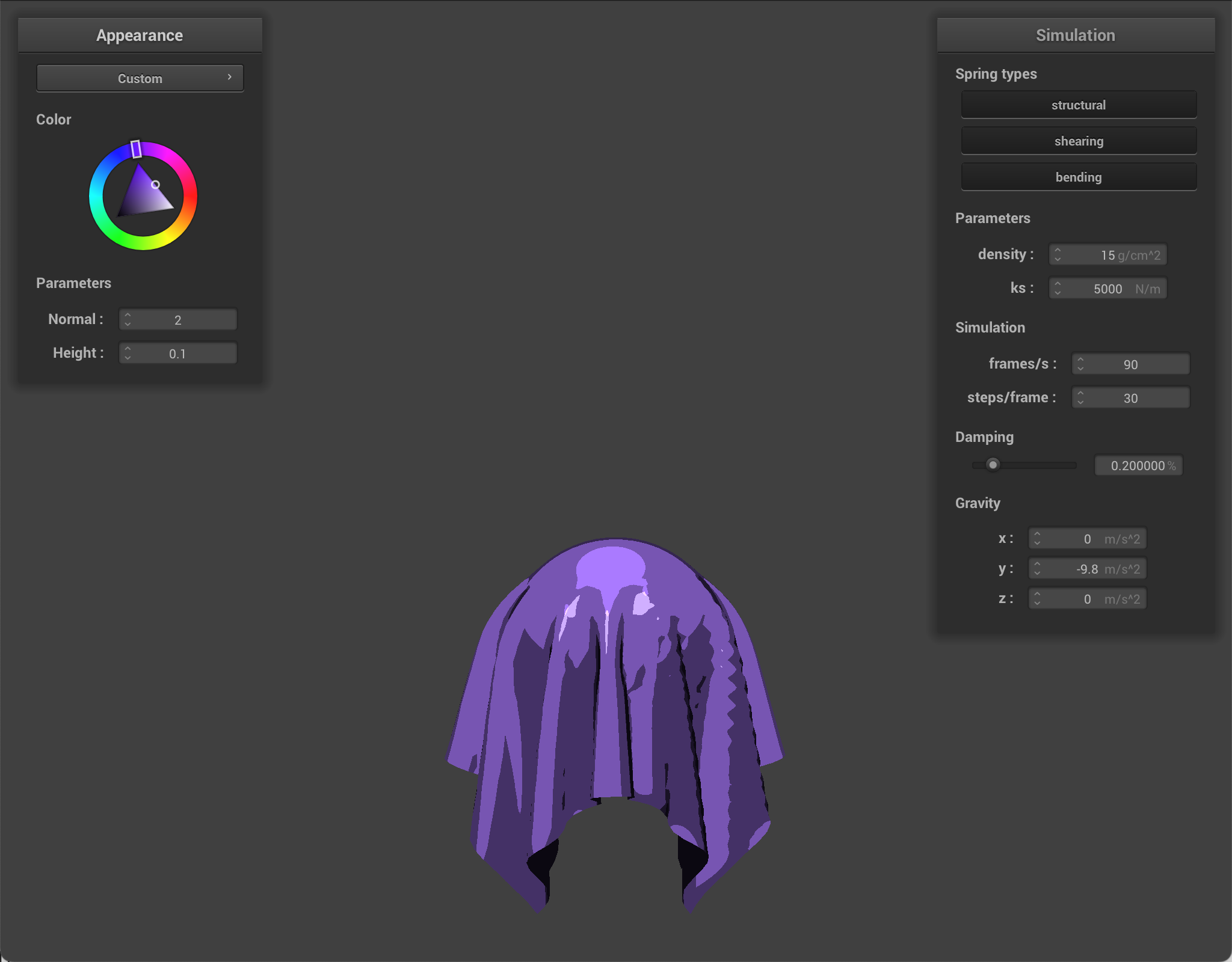
Custom Shader
For my custom shader, I implemented toon shading, which creates a cartoon-like look. The main idea was to compute the usual lighting directions (so the surface normal, light direction, and view direction) but then convert the diffuse into a few specific levels of brightness. This replaced the slow lambert shading that we used to make our shading realistic.
I also added a stylized specular term. The highlight would appear as a sharp bright patch only when the view/light placement is ideal/good enough.
I also outlined shape boundaries. Using the angle between the normal and view direction, I darkened edges. This made silhouettes stronger, and made the shapes look more cartoony.
Finally, I combined all of these components into the final color, using the object's base color as the main tint.
|
|
|
|
|
|
Part 6: Extra Credit——Additional cloth simulation features!
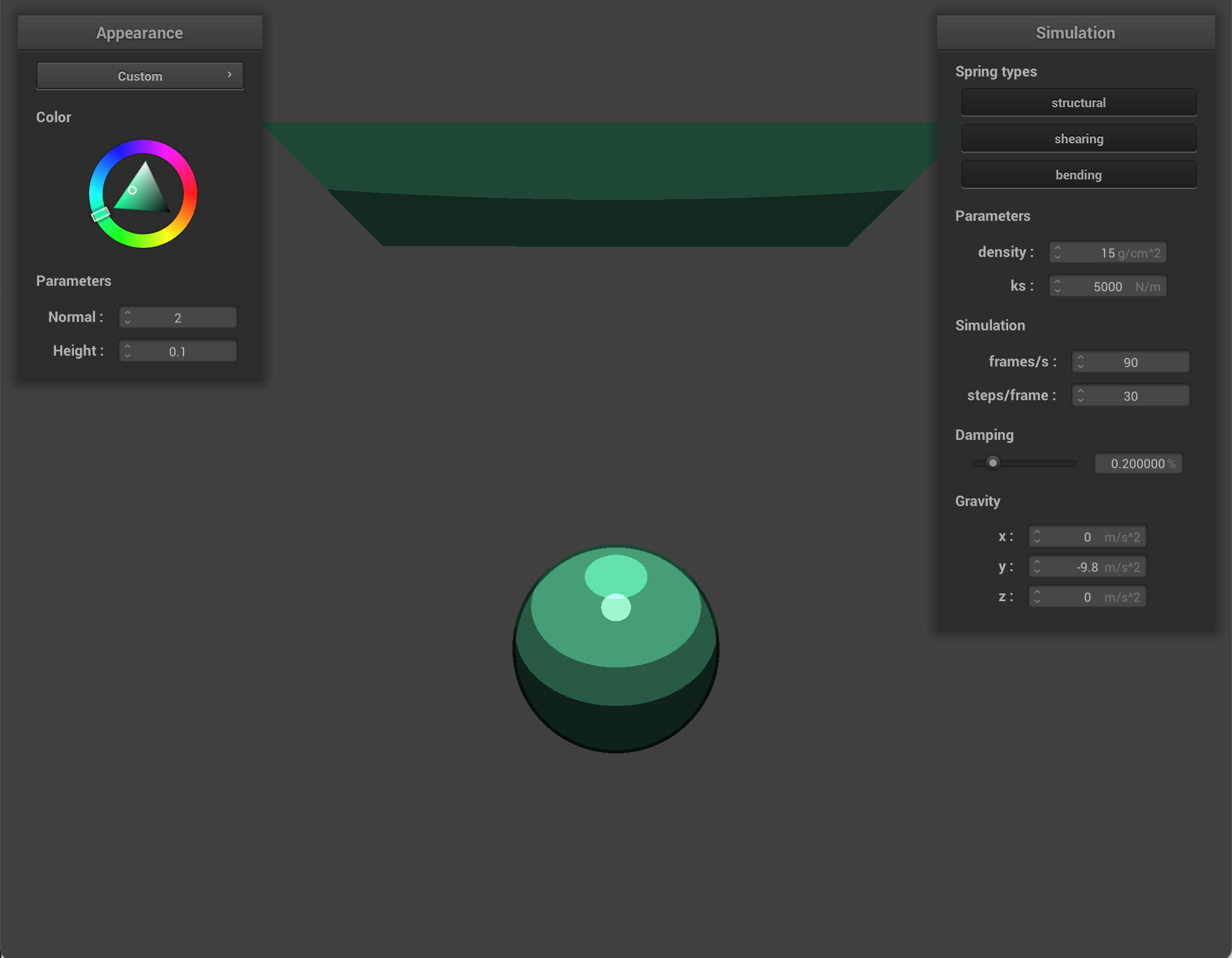
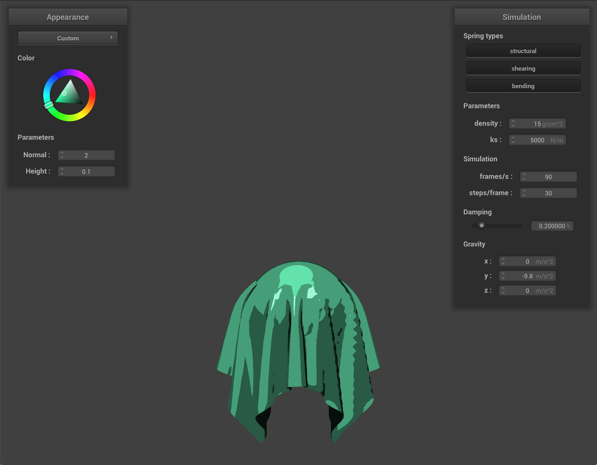
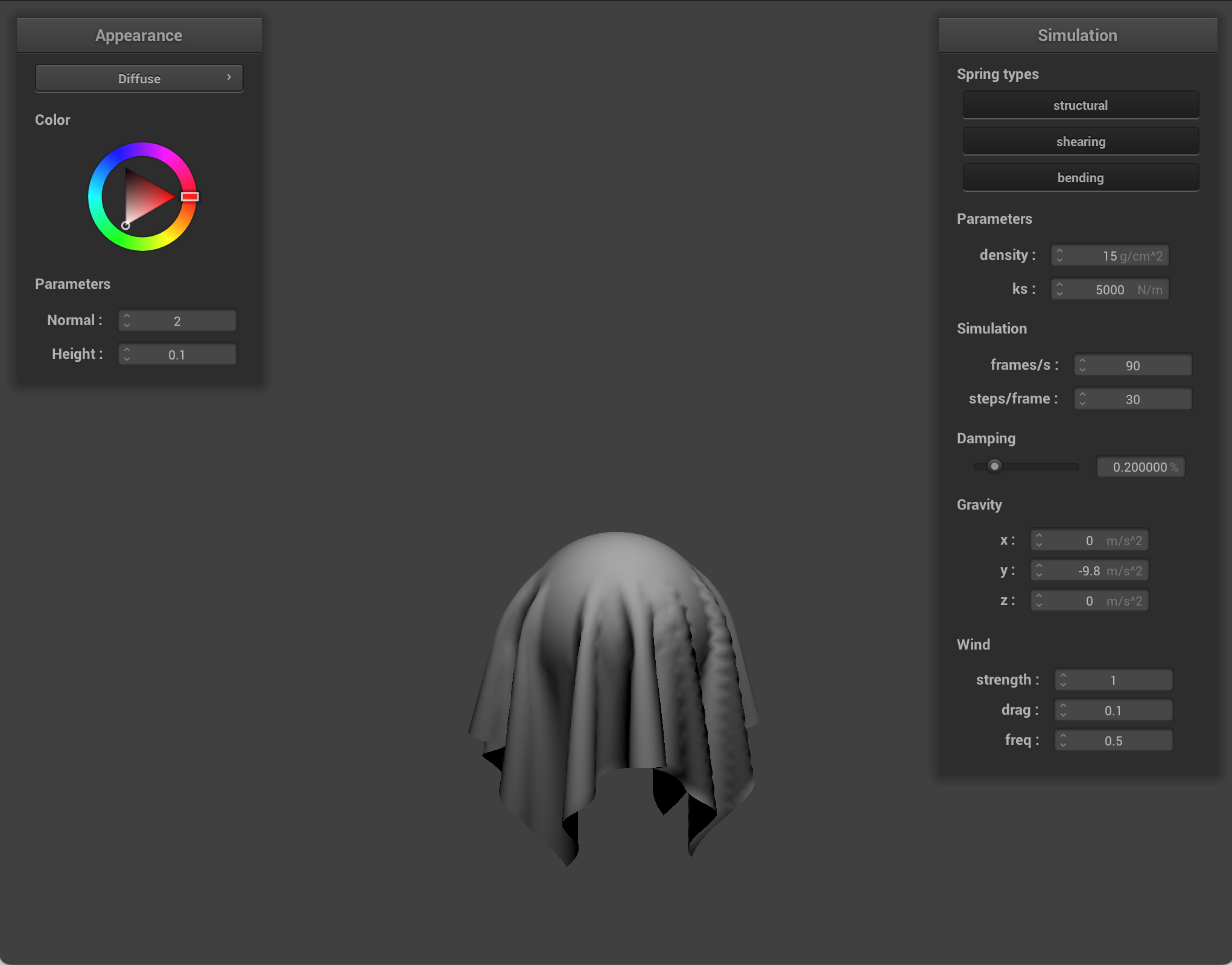
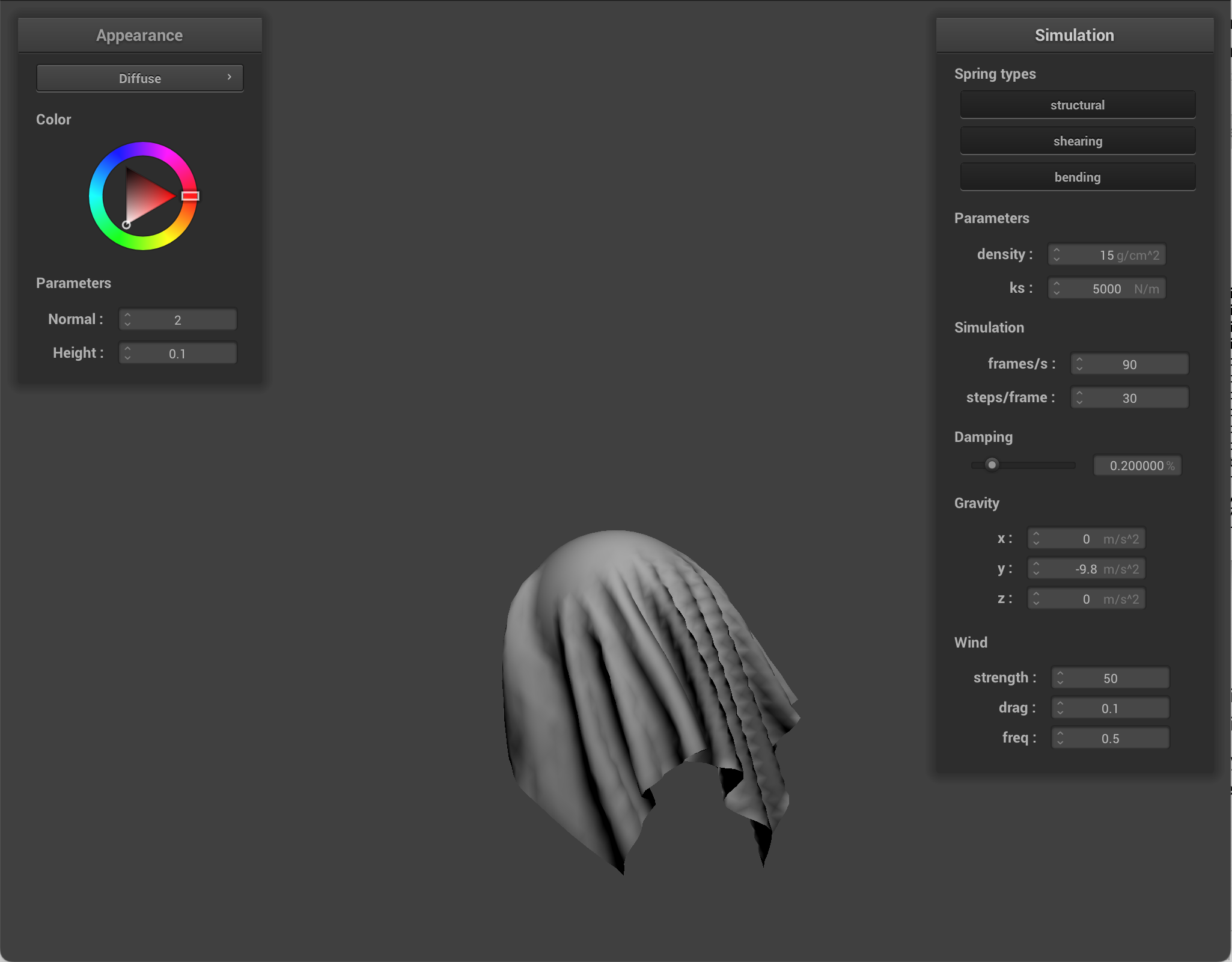
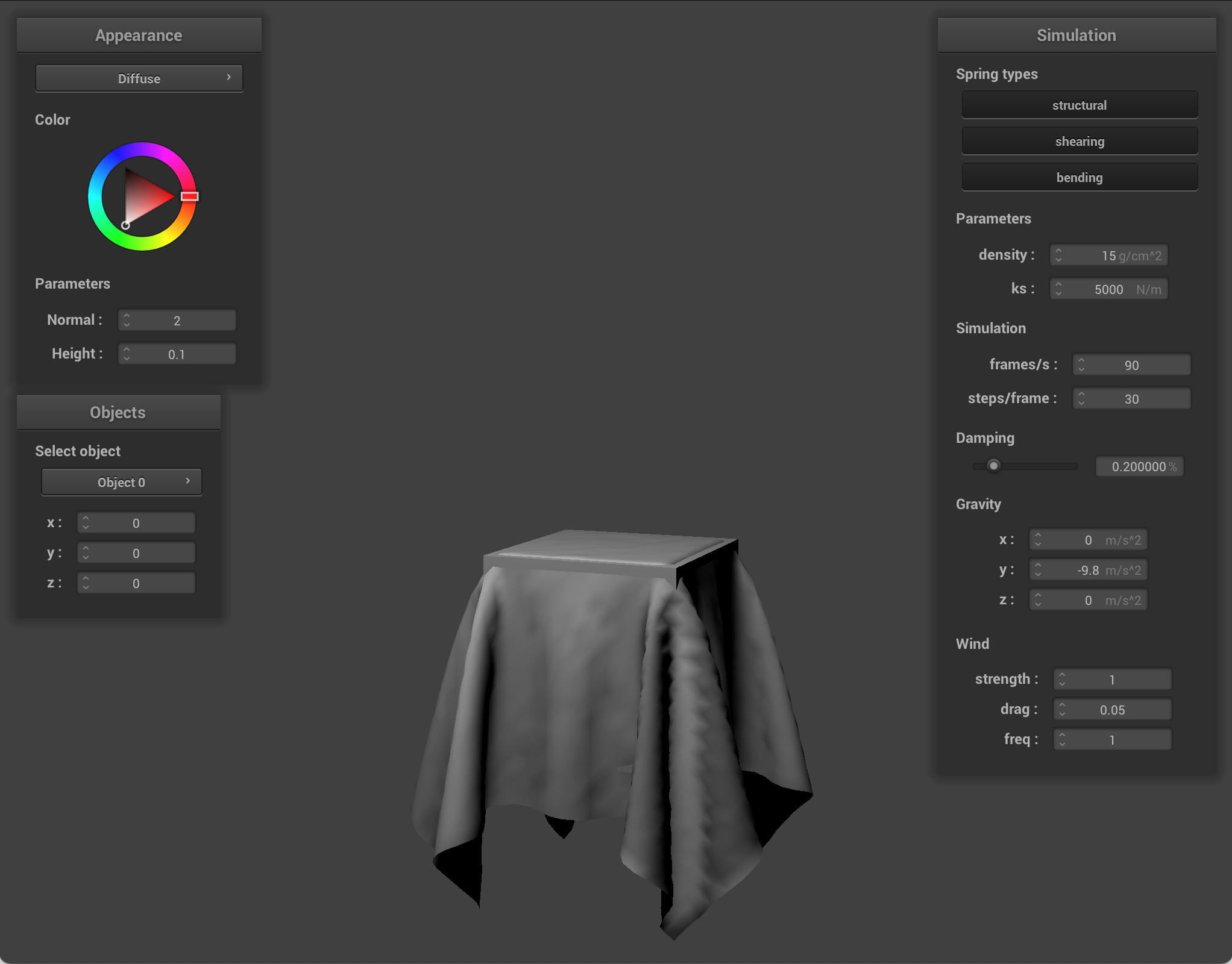
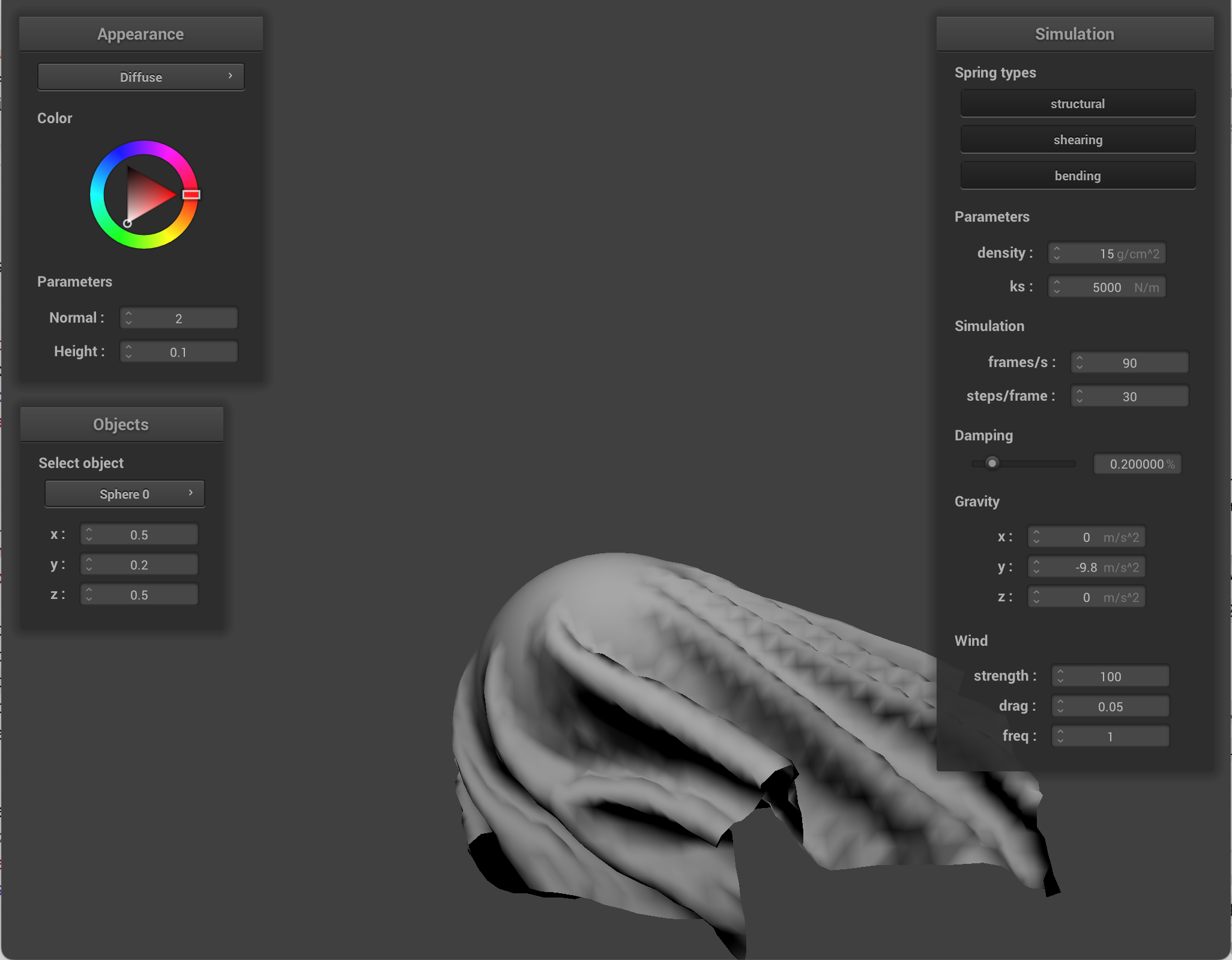
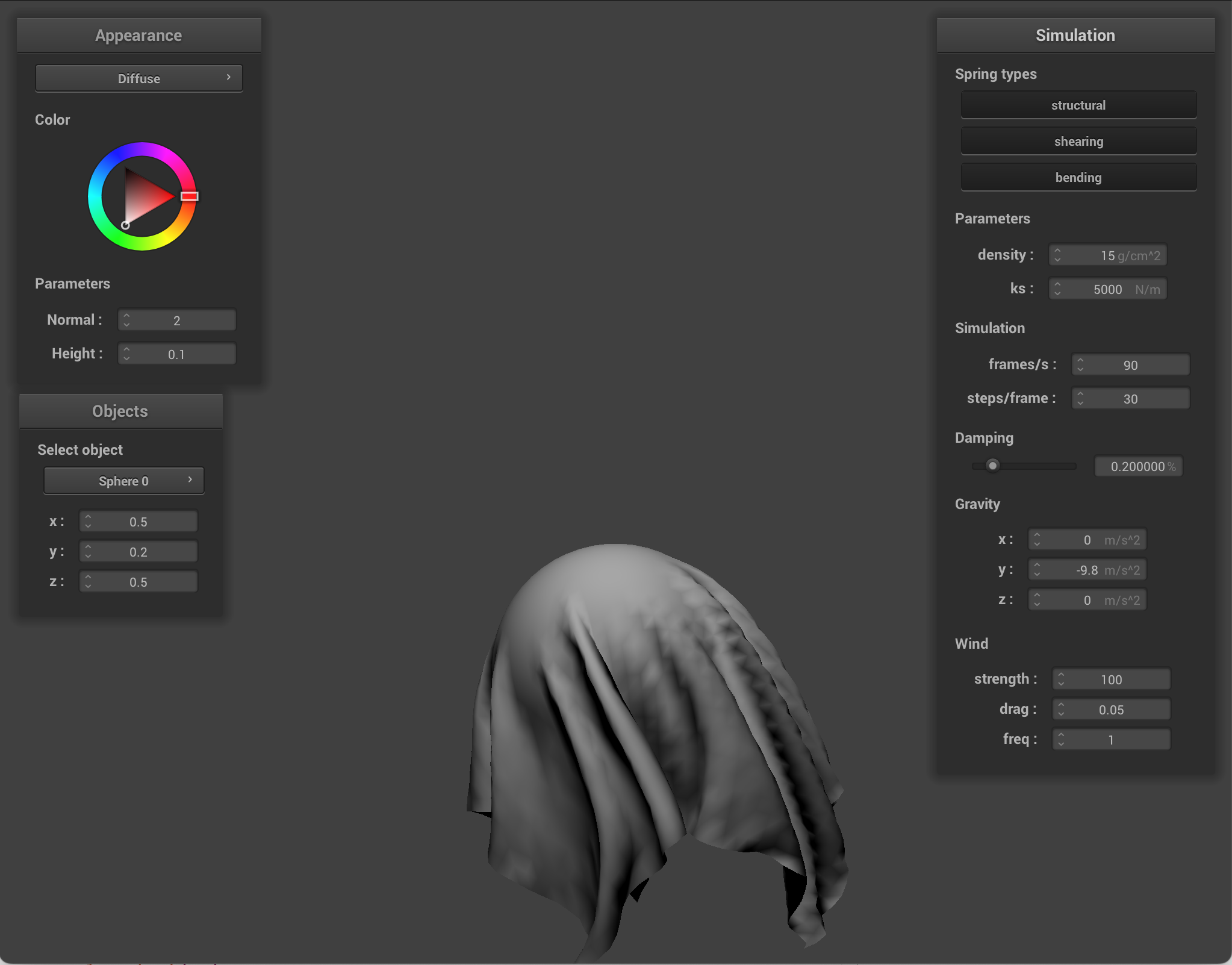
Wind
I implemented wind as a force that is applied during each simulation step inside the cloth physics. So after I add spring forces, I add wind forces. And then integrate positions via Verlet, etc.
To implement wind, for each triangle in the cloth mesh, I compute the triangle geometry from its three current vertex positions, its normal & area, its center, and average triangle velocity. Then I evaluate a spatially varying wind field at that center + time. Then I compute relative airflow as wind velocity minus cloth velocity. I project airflow onto the triangle normal, then scale by wind drag, airflow magnitude, and triangle area. Spatial variation is where wind depends on position, so different cloth regions feel different gusts. Temporal variation is where wind depends on simulation time, so gusts change continuously.
I added a few parameters that can be changed in the GUI.
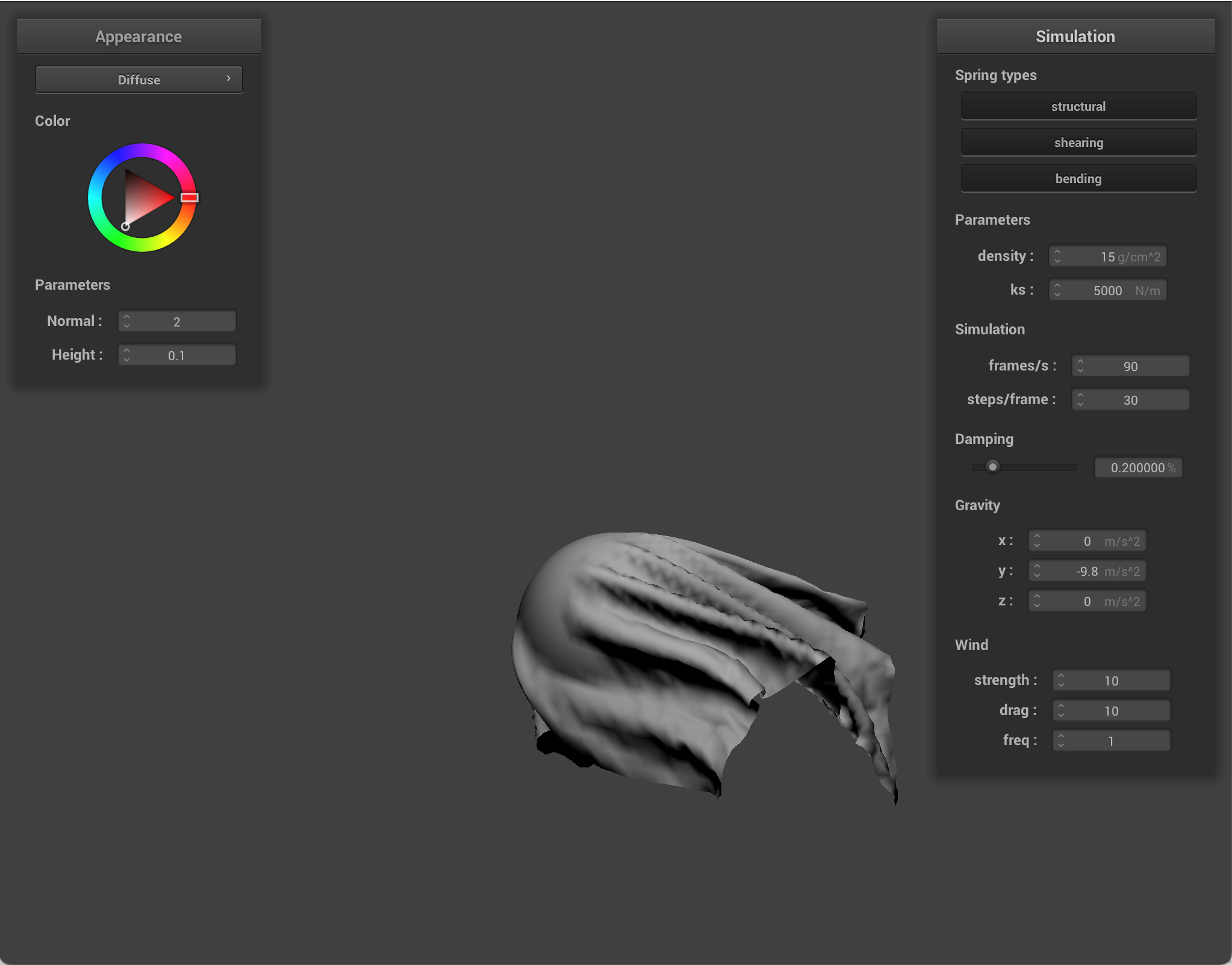
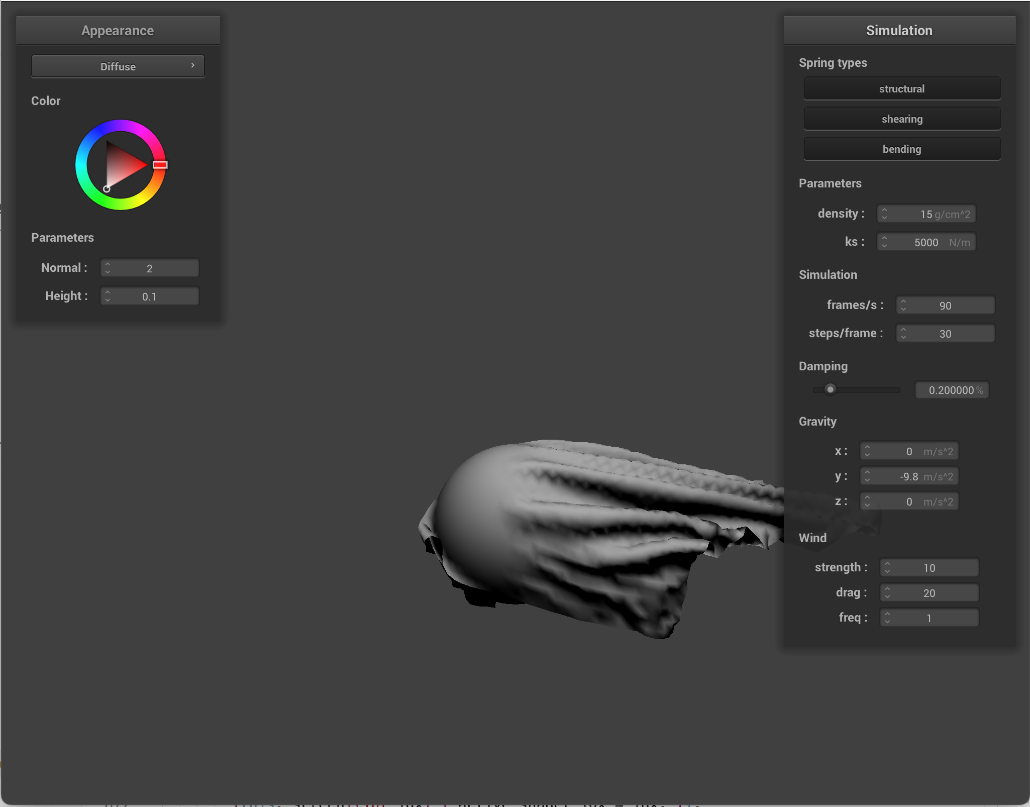
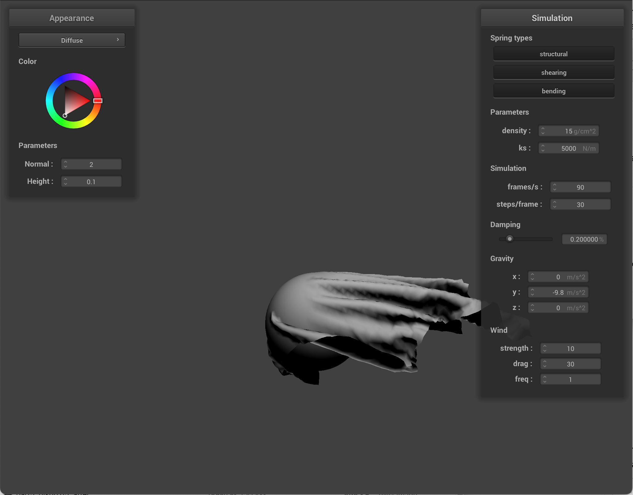
- Wind strength: this controls overall wind magnitude. Lower wind strength means that gravity/spring forces are more dominating. Higher strength means wind forces cause larger displacement, aka the strength of the wind is stronger.
- Wind drag: this controls how much the cloth catches the air (kind of like cloth resistance to air). Low drag means air passes by the cloth with weak effect, and the cloth seems heavier/slower to react. High drag means the same wind/velocity causes stronger force. There is more flutter/movement.
- Wind frequency: this controls how fast the wind gusts change. Low frequency means the wind is slower, with long-period movement. High frequency means quick gust variation, with quick flutter and jittery motion. It was difficult to demonstrate what wind frequency looked like via images.
|
|
|
|
|
|
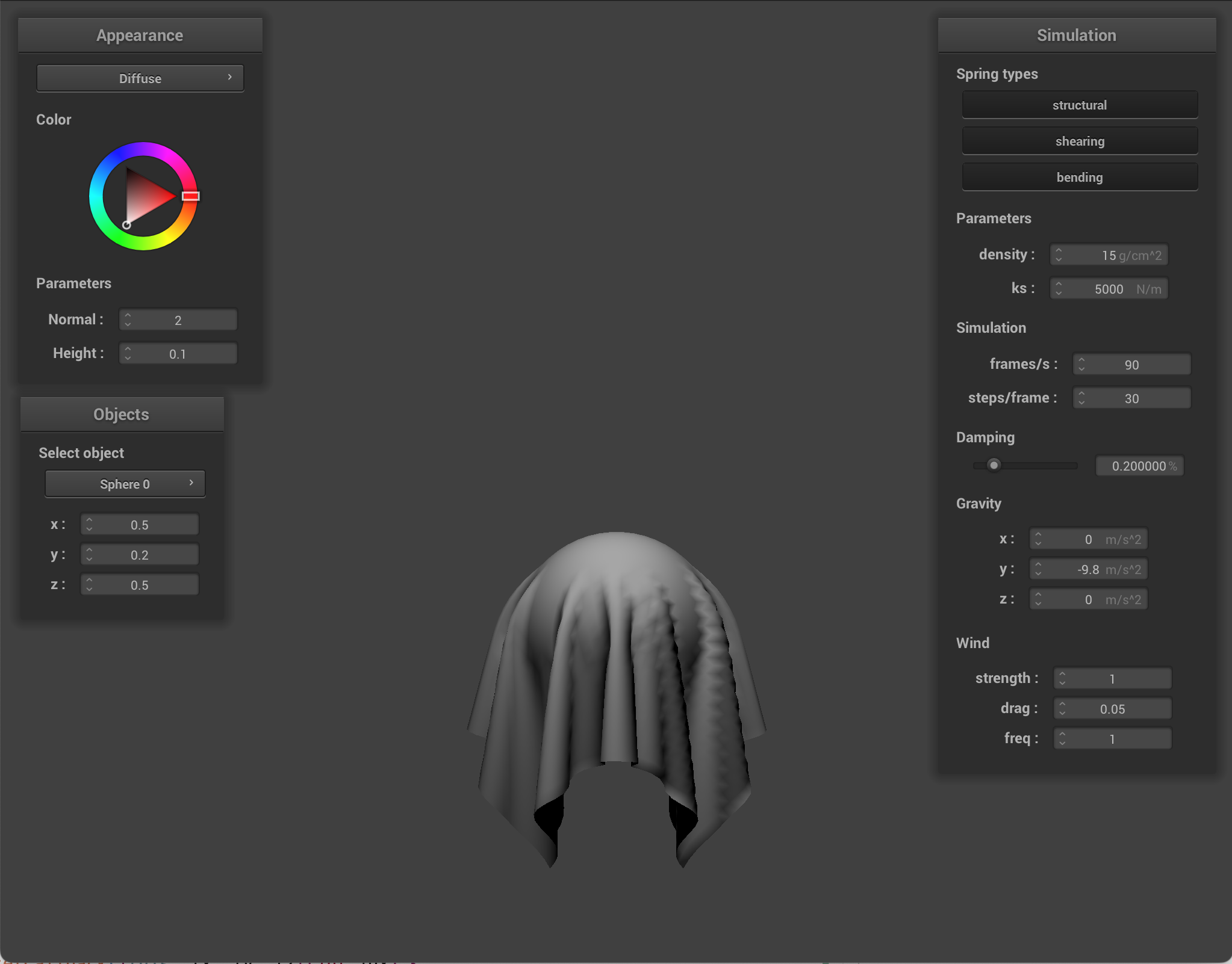
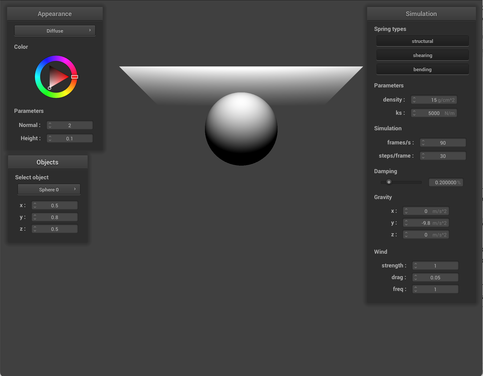
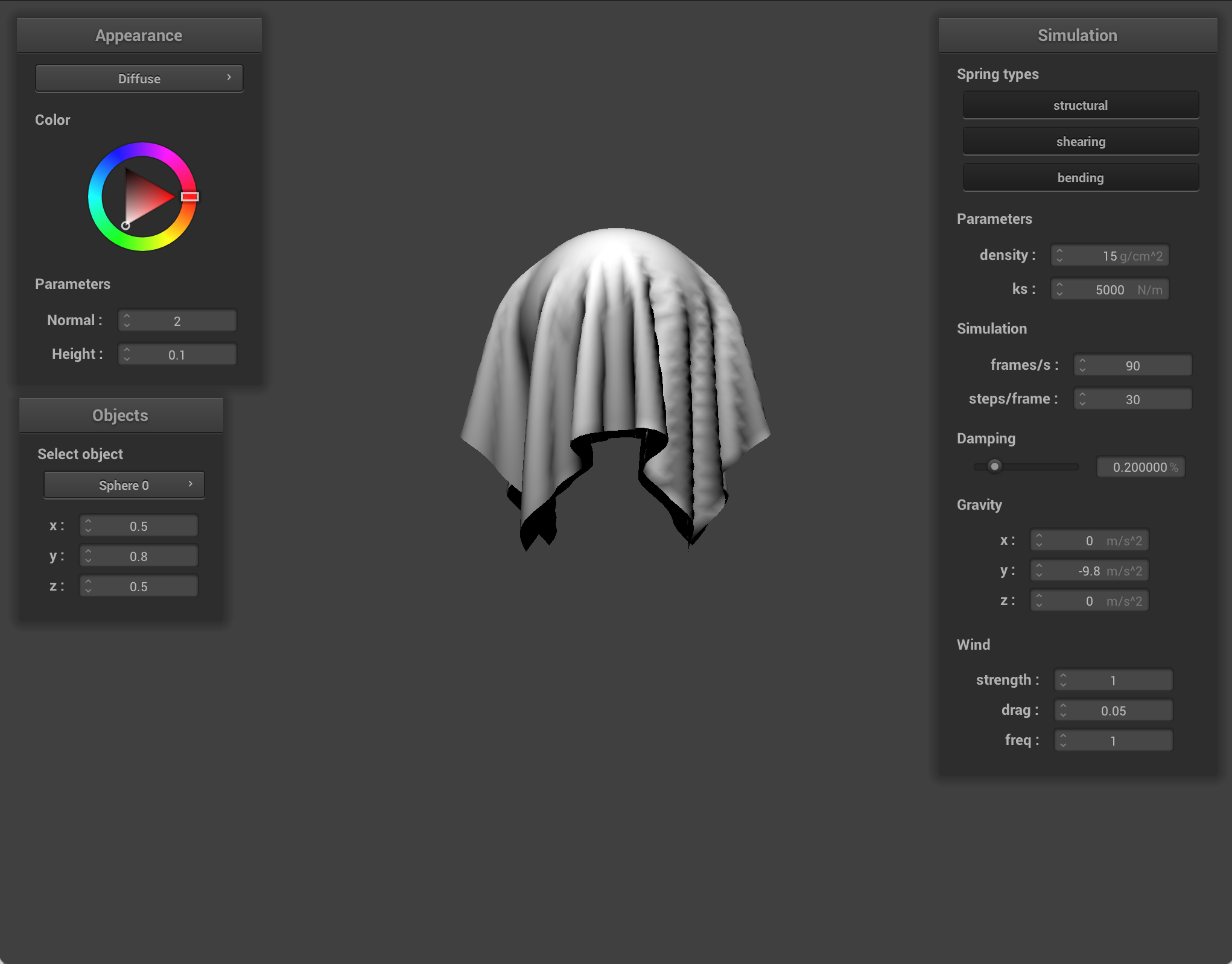
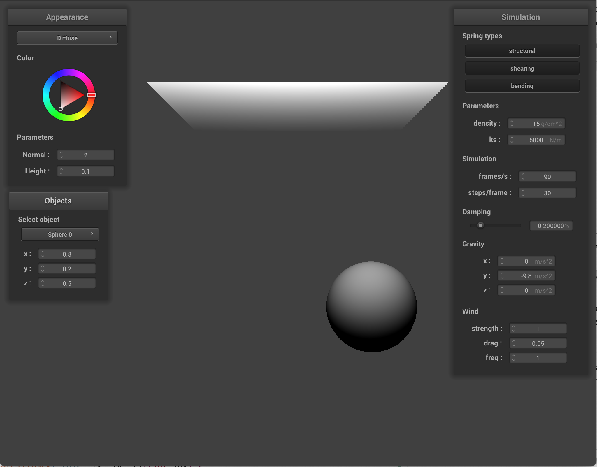
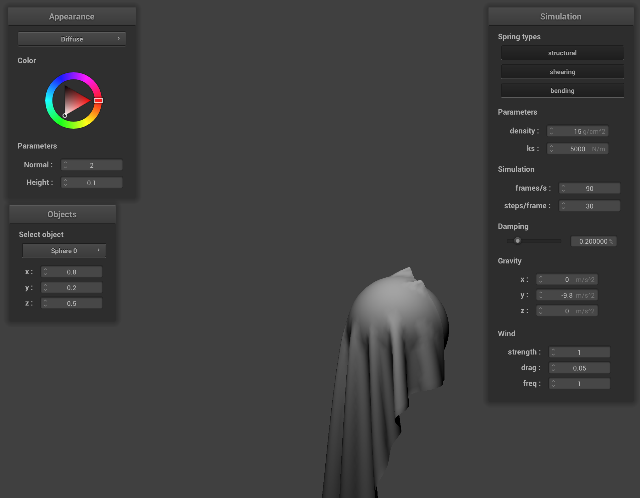
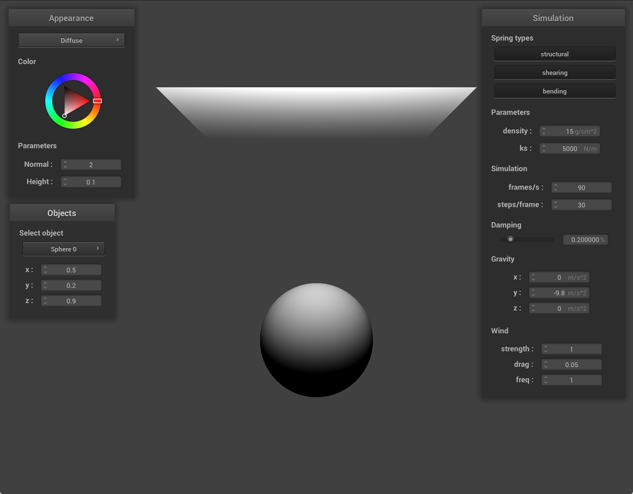
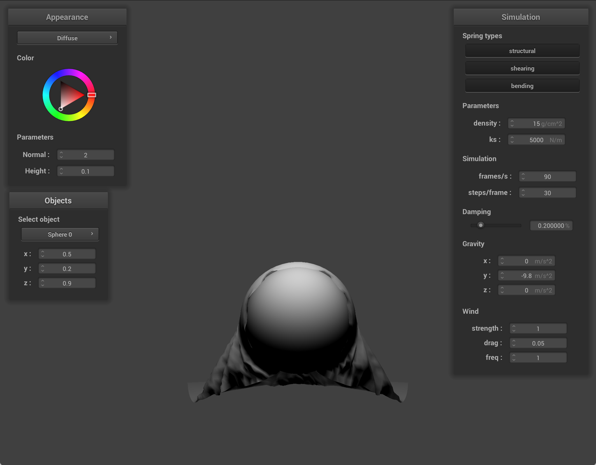
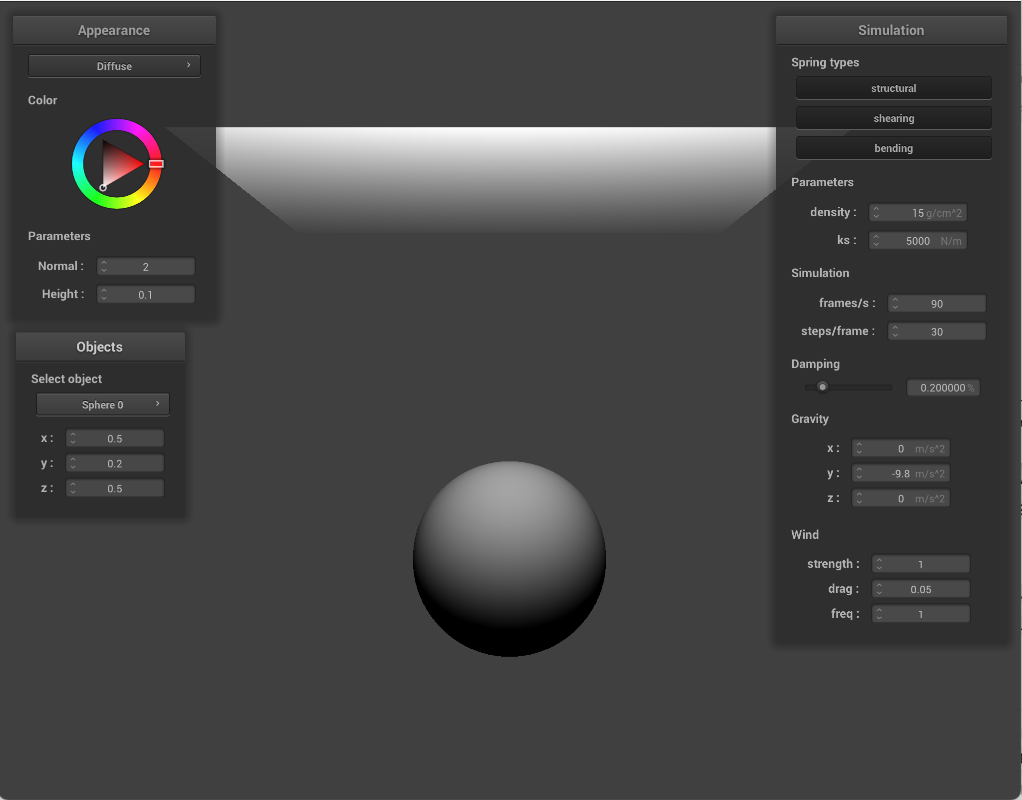
Move objects via GUI
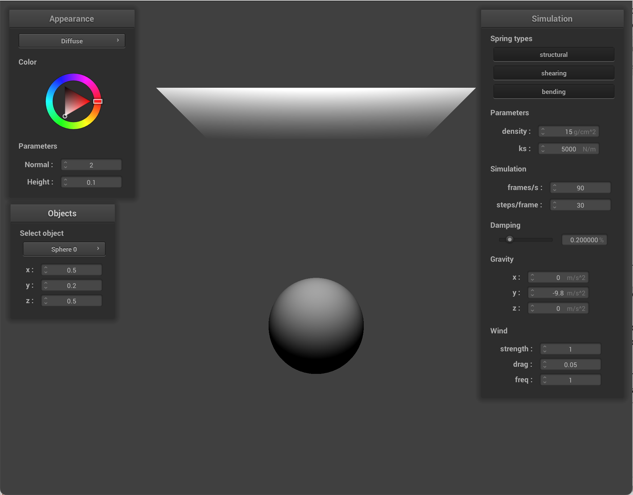
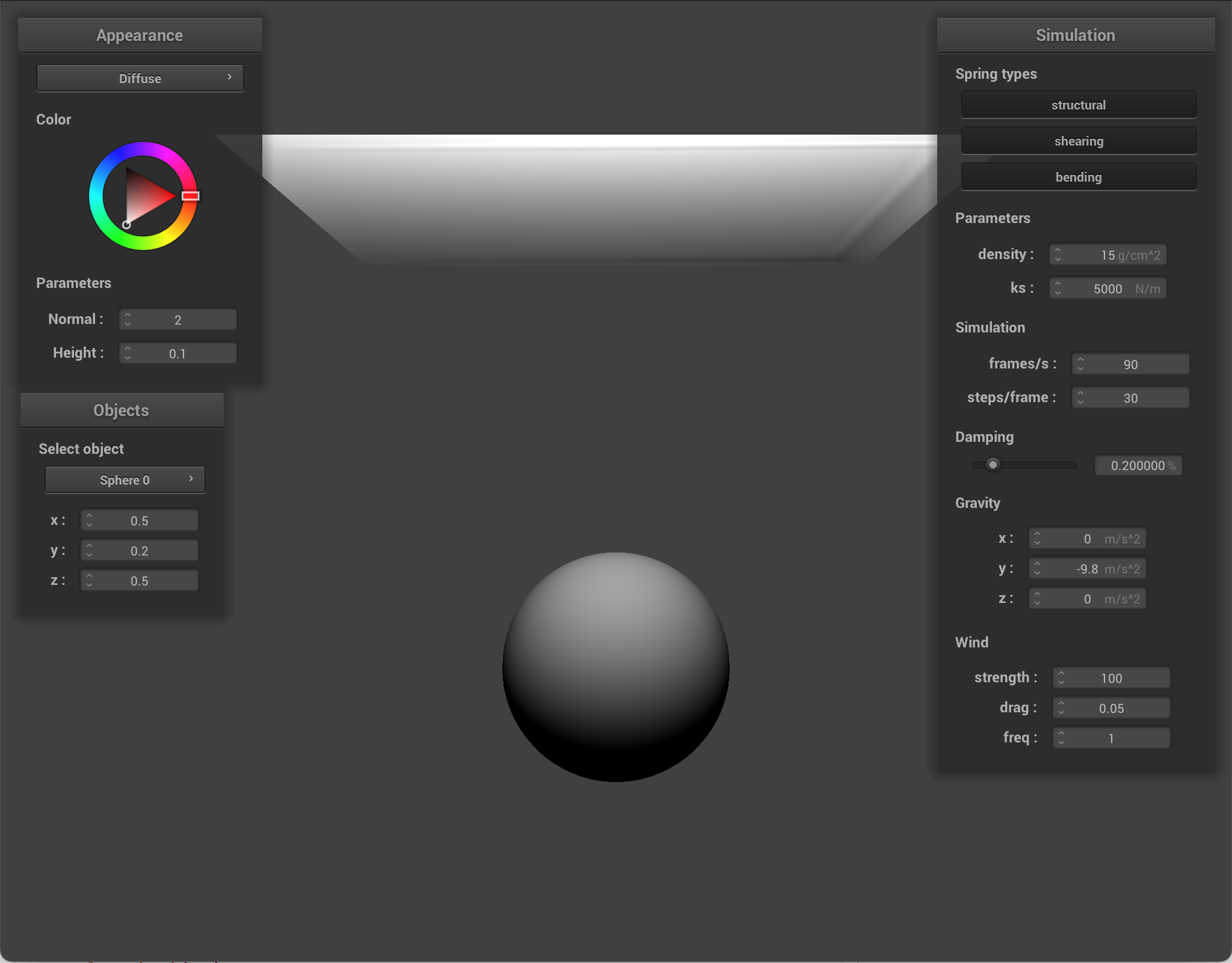
I implemented object movement by adding a new GUI that lets you control the coordinates of the sphere. First, I updated the sphere's methods to be able to access the sphere center (for the GUI). I updated the simulator so it keeps track of which collision object is selected, and I added helper functions to read the current position of an object and write a new position back to that object. Then, I created a new GUI window in clothSimulator. It counts all collision objects currently in the schene, creates editable position controls for x, y, and z, and when any position field is changed, the simulator writes the new position to the collision object. This allows for live responses to the object moving.
|
|
|
|
|
|
|
|
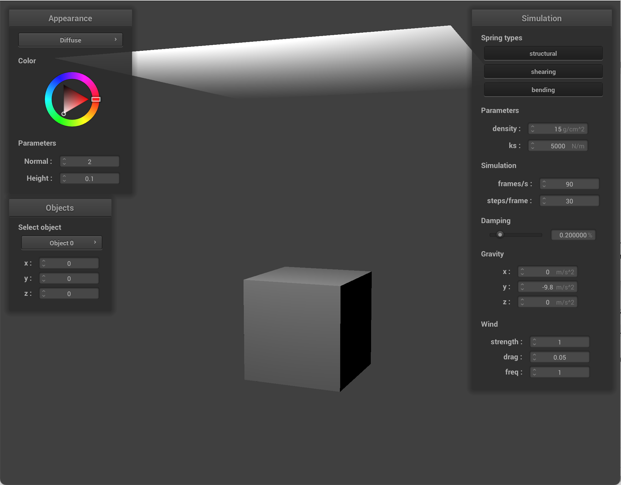
Adding a cube
I created a new collision object type, a cube. I created a new scene object type called cube with a json, similar to the sphere.json. I had parameters center, size, and friction. Then, I created a new collision object class for cubes. The class stores the cube center, half size, and driction. I used half size because that's how collision checks are computed. Then, in main.cpp, I added a check to see if the object type was cube. Basically, I mimicked how sphere was implemented in main, but changed the parameters. In collide, I checked if a point mass was inside the cube bounds, and if so, I chose the nearest axis to project that point out of, alongside a surface offset. The implementation is slightly flawed; in the images, you can see that corners look a bit sloppy.
|
|
Adding hem weights
I added a hem of sorts, so that the boundary point masses are heavier. When building the cloth grid, each point mass is assigned a default mass scale of 1. For each particle, I compute the distance to the 4 edges, and if it's in a certain range (ie if it's close enough), then I increase the mass scale. The increase is strongest at the outermost edge and decreases as you go inward. During simulation, I switched from using one global mass everywhere to using the unique one per point mass. External forces are also affected by this mass scale. This makes heavier edges less responsive to external forces like gravity and wind. As a result, the cloth edges seem to be like a weighted hem. They flap less.
I used wind to show how the hem weights affect how much the cloth is being blown away.
|
|
You can also see how when there are hem weights, those areas fall down faster.
|
|