CS 184 Final Project Proposal | Spring 2022
Bubblz
Thin-Film Diffraction
Team members: Sravya Basvapatri, Tina Li, Simon Tsui, Daniel Won
OVERVIEW
Abstract
In this project, we implemented the ability to render thin-film interference on soap bubble surfaces. To accomplish this, we used award-winning physically-based renderer PBRT, which we found was extremely well-documented.
Our inspiration came largely from two places: the ability to further explore physical rendering and an interest in the beauty of color. In Project 3-2, we all found it extremely interesting how simple it was to understand how new materials interacted with light, and implement a function that models that behavior. Bubbles’ appearance is dominated by three main phenomena: reflection, refraction, and interference. Having combined the former two for glass, we wanted to understand how to implement interference! We also were fascinated by the complex nature of bubbles– they hold a rainbow on their surface, often just for a few seconds, before bursting. Inspired by Professor Ren’s enthusiasm for color and how it relates to the human experience, we found further exploring how the specific wavelengths in light change as they interact with material was extremely interesting.
To model this in PBRT, we modified the reflection and transmission effects for glass material. Specifically for reflection, we created a Specular Interference BSDF that processes the light intensity on a given sample surface interaction to produce the rainbow patterns at the exiting ray. Taking equations, theories, and explanations from various research papers, we implemented these mathematical models of taking in the incident light intensity and the Fresnel term that produced certain RGB values for different samples on the bubble’s surface. Our results were an approximation– rather than using spectral rendering, we stayed with sampling at R, G, and B values. In our results, we were able to render images of translucent bubbles that displayed gradients and rainbow patterns of varying colors.
DEMO VIDEO
TECHNICAL APPROACH
Technical Approach
In the real world, soap bubble surfaces display rainbow wave patterns in response to the light waves within its surrounding environment. This phenomenon is due to a physical concept called thin-film interference, which we implemented for this project. Thin-film interference combines the phenomena of reflection, refraction, and transmission as it involves constructive and destructive interference of light waves. This interference effect is both wavelength dependent and dependent on the width of the bubble which varies over its surface, thus resulting in the patterns that we see.
Andrew Glassner’s papers on soap bubble simulation and rendering effectively describe the mathematical properties of how light moves through the soap bubble film and how it affects the colors reflected to our visual system. The phenomena comes down to how light rays superimpose, and how their phase depends on their wavelength and the bubble’s thickness. To simplify this, there’s three main categories of interference:
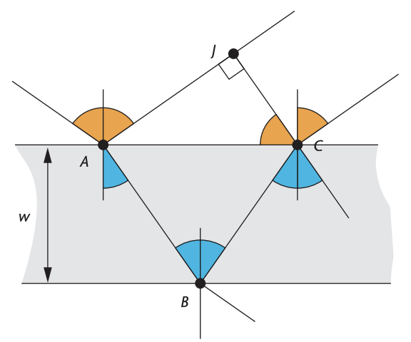
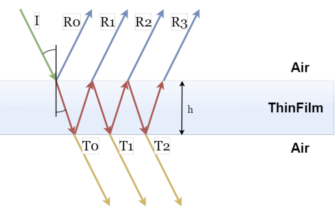
To model this, we needed to come up with a relationship between the effective optical path length of a light ray that hits the bubble with a given intensity value and wavelength. Just like in glass, part of the light reflects off the surface at a perfect specular angle (aka the angle of incidence θi), and part of the light refracting through the thin film (with a higher index of refraction around 1.3) at an angle theta_t (θt). At the inner surface of the bubble, some light again transmits through, while other light bounces back to the outer surface. This process repeats infinitely, but we can come up with an equation to represent the light intensity as a result of R0…Rn.
As explained above, the phrase shift depends on the difference in the effective optical path length between a reflected ray Ri and the other reflected rays. In order to derive this, we can use trigonometry. From there, we relate the path difference to a phase shift, then to the amplitude of the exiting wave, and finally, to the intensity.
Find the optical path difference!
d = η(AB + BC) − AJ + λ/2
d = 2wηcos(θt) + λ/2
Convert this to phase shift
δ = 2π / λ * d
Find total amplitude
AR = A + Aeiδ
Intensity is amplitude squared
Ir = 4A2 cos2(δ/2)
Simplify and implement!
Ir = 4IiRFsin2(2π / λ * 2wηcos(θt))
Above, w is the thickness of the bubble, η is the index of refraction inside the thin-film, λ is wavelength, and RF is the reflective coefficient. Now that we have derived the equation for the intensity of light, we can then implement it.
Techniques Used
To implement this in PBRT, we had to create a new unique material for a bubble. For new PBRT materials, there are two main functions to implement based on the documentation provided for the PBRT codebase by Matt Pharr et al.: ComputeScatteringFunctions and CreateBubbleMaterial. ComputeScatteringFunctions determines what BSDFs we should add based on its arguments. The arguments including si, a pointer to a SurfaceInteraction object that represents a point on a given object’s surface that we want to render, arena, a MemoryArena object that stores the BSDFs, and mode, which describes whether the surface intersection is a result from a camera ray or a light ray from a light source. The CreateBubbleMaterial function then reads arguments from a .pbrt scene file (which is the file format rendered by PBRT) and returns a new material object with these arguments.
In the ComputeScattering Functions, we used the glass material (provided in the base code) as a starting point in which two BSDFs were used (named SpecularTransmission and SpecularReflection). We altered the SpecularTransmission effect to simulate a light ray going from air to air– there is no change in the index of refraction, and this gives the bubble its transparent appearance. We then replaced SpecularReflection with SpecularInterference, implementing an entirely new BSDF to capture the wavelength and width dependent interference effect derived above based on Glassner’s paper.
The SpecularTransmission BSDF takes in four arguments:
The SpecularInterference BSDF takes in two arguments:
Within reflection.cpp, we implemented the SpecularInterference BSDF using the following intensity equation.
Ir = 4IiRFsin2(2π / λ * 2wηcos(θt))
For the variables, we chose w to be a constant value of 500 nm (which was a general thickness value for soap films) as a starting point with potential for variability, and η to be around 1.3 or 1.4 which was stated to the approximate index of refraction for soap (Glassner 101).
While we primarily used a lot of the mathematical analysis provided by Glassner, we implemented an altered, simplified version of Glassner’s approach (which originally involved calculating the intensity of the reflected wave at every 5 nm of wavelength between the minimum and maximum wavelengths of the visible spectrum from 380 to 780 nm) in order to calculate the R, G, and B values. Instead of using 81 different sets of wavelengths, we simplified into just using three sets: red, green, and blue. We calculated the following intensities for each color component (using the general simplified equation for reflected intensity) and assigned these values scaled by cos(theta_t) to an RGB Spectrum object that represented the color reflected at a given sample point:
Ired = 4 * Ii[red] * RF[red] sin2(2π / 630 * 2wηcos(θt))
Igreen = 4 * Ii[green] * RF[green] sin2(2π / 532 * 2wηcos(θt))
Iblue = 4 * Ii[blue] * RF[blue] sin2(2π / 465 * 2wηcos(θt))
RGB = (Ired, Igreen, Iblue) / cos(θt)
Problems Encountered
One of our earliest problems was deciding what renderer to use for our project. Upon consultation with the course staff, there were a few options that we considered including refurbishing our project 3 Pathtracer codebase or utilizing dedicated renderers such as mitsuba and PBRT. The process of building and working with mitsuba resulted in a lot of issues and confusion with builds unable to work due to a lack of sufficient documentation and a necessity of several external frameworks and libraries. After a week of trying to debug the codebase, we decided to move on to the PBRT renderer which had considerably a lot more documentation and resulted in less building issues.
With getting accustomed to the PBRT codebase, we ran into quite a bit of difficulty addressing errors. Even though PBRT is well documented, it felt like it was not well documented enough. We had a hard time figuring out how to add a new material class which led to each of us having to rebuild, recompile, and even reclone the PBRT source code many times.
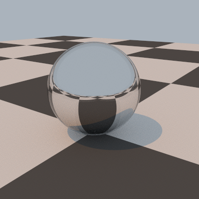
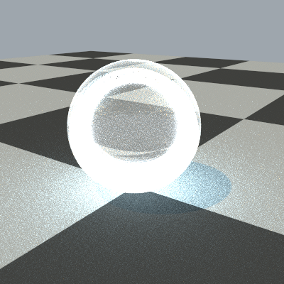
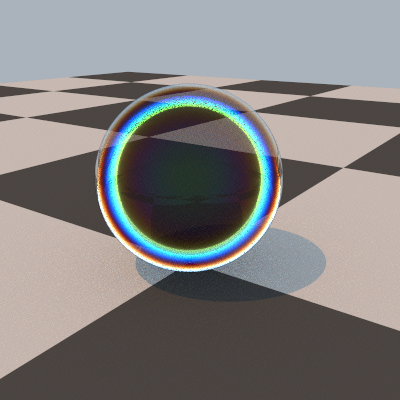
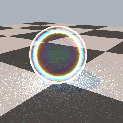
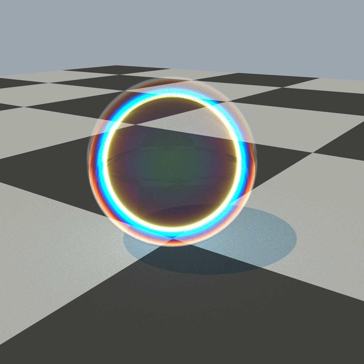
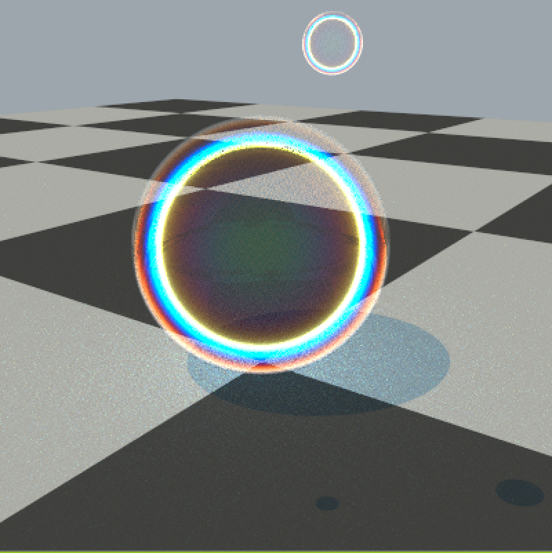
Achieving an accurate rendering quality was also a major difficulty throughout the project timeline as we encountered unexpected properties within each subsequent render. Taking into account the concept that the soap bubble had a soap film with a given thickness as well as a volume of air enclosed by the film, we first created two spheres, a mirror sphere on the inside and a glass one encasing it (1). Then, we figured out that we can minick having a ball of air inside the sphere by setting the inside sphere’s refraction to 1 (2). We then implemented wavelength dependencies to get the rainbow colors inside the bubble (3) and played around with some parameters to get our soap bubble (4).
Render Progress
1: Fushigi Ball | 2: “Holy Bubble” |
3: UnHoly Bubble | 4: Rainbow Holy Bubble |
Lessons Learned
Working with a new renderer and codebase turned out to be a lot more difficult and time consuming than initially expected. A majority of our working timeline was used to figure out building different renderers to see what would work best with our project as well as understanding how to work with the renderer. Therefore, we learned an important lesson to not underestimate the time it takes transferring to unfamiliar tools and how it is never too early to start on a project, especially one dealing with complex concepts like this one.
Additionally, we also underestimated the difficulty of wavelength dependent rendering when devising our work plan. However, the challenge that came with learning deeply about this phenomenon gave us much further insight into how light interacts with objects in our environment beyond the scope of what the course taught us so far about these interactions.
One of the coolest lessons was understanding how complex realistically modeling bubbles is! While we focused on the phenomenon of interference and how it emerges from reflection and refraction inside of a thin-film, there are also many other factors at play that we need to take into account to create an accurate bubble model. For example, in order to accurately model the thickness of the bubble’s surface, we need to use principles of area-minimization and Navier Stokes. Often, the thickness is just modeled using Perlin noise, almost destroying the care that went into deriving an exact equation for the wavelength-dependent light scattering.
RESULTS
REFERENCES
Glassner, Andrew. “Soap Bubbles: Part 2.” Andrew Glassner’s Notebook.
https://www.glassner.com/wp-content/uploads/2014/04/CG-CGA-PDF-00-11-Soap-Bubbles-2-Nov00.pdf
Pnarr, Matt et al. Physically Based Rendering: From Theory to Implementation. 15 Oct.
2018. https://www.pbr-book.org
CONTRIBUTIONS
Sravya:
Tina:
Simon:
Daniel: