Project 3-2 | Pathtracer
Name: Star Li | SID: 3033789672
Overview
In this truncated version of Project 3-2, we further implement some advanced features in ray tracing. For me, I chose to add Mirror and Glass Materials and Depth of Field. In
the former feature, I took advantage of the physical properties of light and materials, adding the corresponding BSDF for mirror and glass materials. Reflection and refraction are also added that
make the rendered scene more realistic. In the later feature, we abandoned the original pinhole camera model and adopted the more common thin-len model. This brings in concepts such as
aperture and focal length which can be tuned around to give interesting focusing effects.
Overall, this project is much shorter and easier (since I've got accustomed to working with C++) than the previous ones. It once again impresses me as many seemingly complicated physical phenomenal such as lighting and refraction can be nicely simulated/approximated by computer once you understand the math/physics behind. This part of the project also gives me several hints on potential topics for the final project.
Part 1: Mirror and Glass Materials
In this part, we achieve some interesting effects on a mirror sphere and a glass sphere.
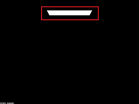
M = 0 is a trivial case since we don't even have direct lighting with zero bounce. Everything in the scene which is not a light itself (get_emission returns zero) will be black.
M = 1 unlike the diffuse sphere which shows some color with direct lighting, our glass and mirror spheres remain mostly black since these materials themselves don't emit any color. Instead they need to bounce off incident rays from surrounding environment to our eyes (camera). However, since we only allow one bounce in this case, only parts that reflect light ray in M = 0 (i.e. the area light itself) can be seen.
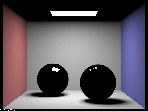
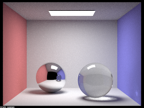
M = 2 the mirror ball is able to reflect the scene we saw when M = 1, the glass ball whereas is still quite dark since only a portion of rays get reflected, the refracted lights are still trapped inside the sphere at this stage. Also the overall lightness is brighter due to more bounces among the scene.
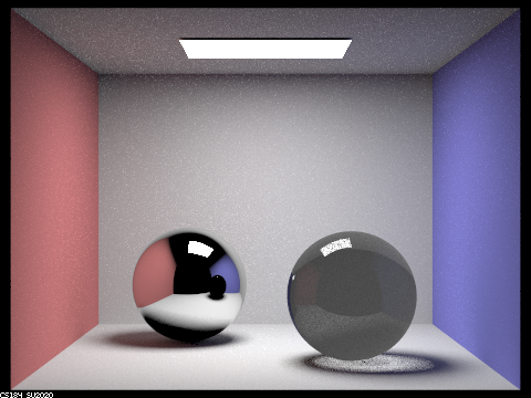
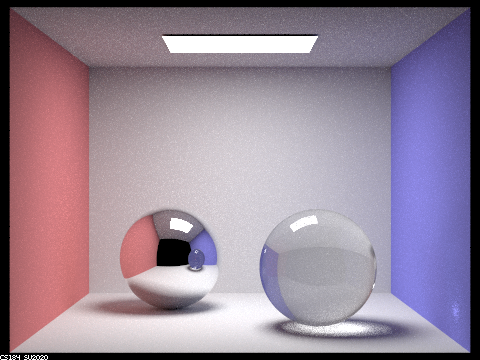
M = 3 the overall scene is even brighter. We can observe that both the mirror and glass balls are brighter, the later effect is due to refracted lights can now get refracted again off the sphere and transmit light.
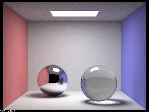
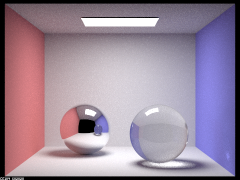
M = 4 we can now see the highlight cast by the glass sphere on the blue wall, which is the result of many bounces from light source. The glass ball itself is also brighter.
M = 5 there isn't much major differences with M = 4. However, we observe a detail that the ceiling mirrored by the mirror sphere is lighter than before.
M = 100 at this stage all the light reflections and refractions converge (most of the lights are stopped by Russian roulette). I honestly cannot tell much difference with the M = 5 case.
Part2: Depth of Field
In the first part of Project 3, we assumed a pinhole camera model and built up our path-tracing algorithm on top of that. This is, however, not our eyes or real-world camera works. In this part, we
will implement a better approximation (still) -- the thin-len model. Everything that can be captured by a pinhole camera is in focus, which is not the case in the thin-lens camera. Basically, all light rays
that goes into a certain pixel in a pinhole camera has a direction from a fake "camera origin" (0, 0, 0) to it; in a thin-len camera since we get an entire thin lens instead of a origin point, we need to sample point on the lens
and multiple rays of different direction can enter the same pixel. Below are some examples of using this thin-len model with different aperture and focal lengths.
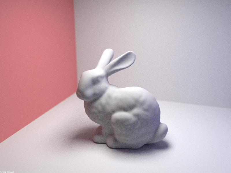
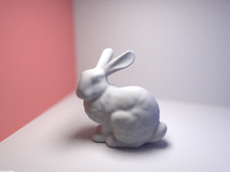
Varying focal lengths
pixel sample rate = 32, light sample rate = 4, maximum depth = 5, aperture = 0.5


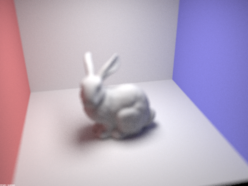

Varying aperture
pixel sample rate = 32, light sample rate = 4, maximum depth = 5, focal length = 2.5


Made with ❤ with Bootstrap, by Star Li (listar2000@berkeley.edu) My Website