Project 2 | MeshEdit
Name: Star Li | SID: 3033789672
Overview
This project is about the implementation of some mesh geometry structures. In the first part (Part I and II), I implemented the Bezier curves and surfaces
, which are powerful structures to represent smooth curves/surfaces in space with varying number of control points. In the rest of the project, I mainly worked with
the half-edge data structure. Some local operations, such as vertex normal and edge flip/split, are implemented first and followed by the very important
global loop subdivision algorithm, which enables smooth mesh upsampling.
Overall, this project brings me deeper understanding of OOP and data structure in C++, which I seldom worked with before. It also practices my debugging skills as the
half-edge data structure is complex and involves multiple components. I'm especially impressed by the effect of applying simple algorithms (loop subdivision, vertex normal
calculation etc.) on the mesh geometry and their execution speed.
Task 1: Bezier Curves with 1D de Casteljau Subdivision
Steps for implementing de Casteljau's algorithm to calcualte Bezier Curves
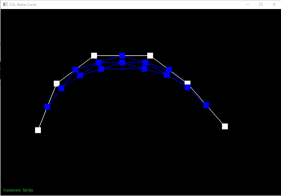
We start off implementing the BezierCurve::evaluateStep function, which performs a one-step update in the construction of the curve. This function takes in a list of
ncontrol points (or intermediate points). So in a for-loop, we take in consecutive two points u and v, then take thelerplerp (linear combination) of them u * (1 - t) + v * t to be the points for the next step. This function finally returnsn - 1such points in a vector.Once we finish the first step, the whole de Casteljau Subdivision algorithm just recursively calls the above function to compute the points until the returned vector only has a single element, which is our desired curve lies at with parameter
t. Varying this parameter from 0 to 1 should give us a complete curve.
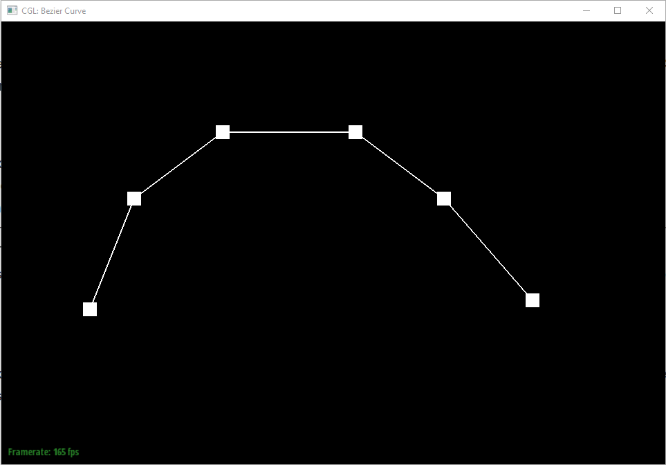
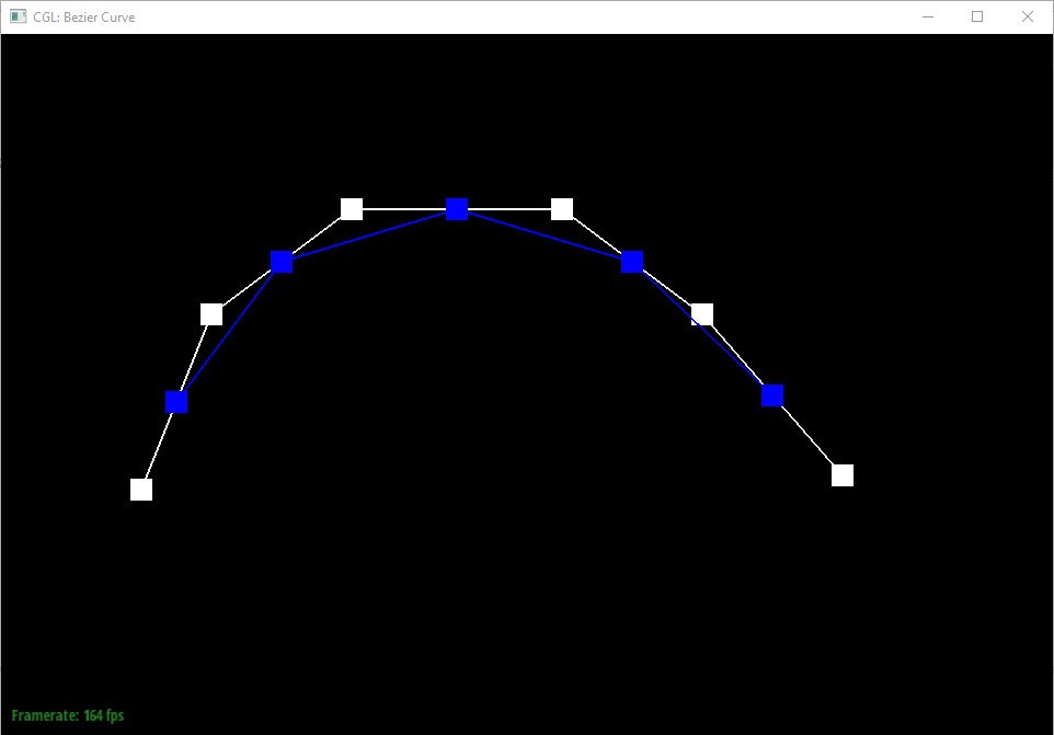
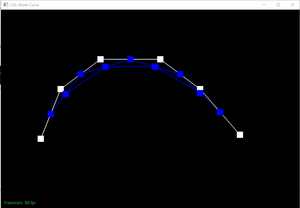
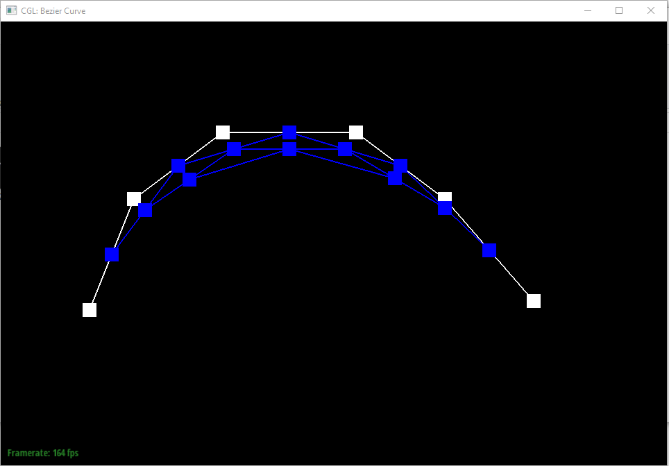
Bezier Curve at different evaluation level
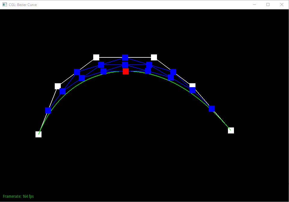
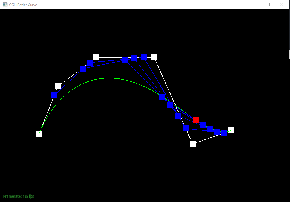
Slightly different curve at different parameter t
Task 2: Bezier Surfaces with Separable 1D de Casteljau
Extending de Casteljau algorithm to Bezier surfaces
The first two methods for this task, BezierPatch::evaluateStep and BezierPatch::evaluate1D are very similar to the simple 1D case and correspond to step I and II in the above descriptions. Putting together they allow us to derive a Bezier curve with a list of control points at parameter t.
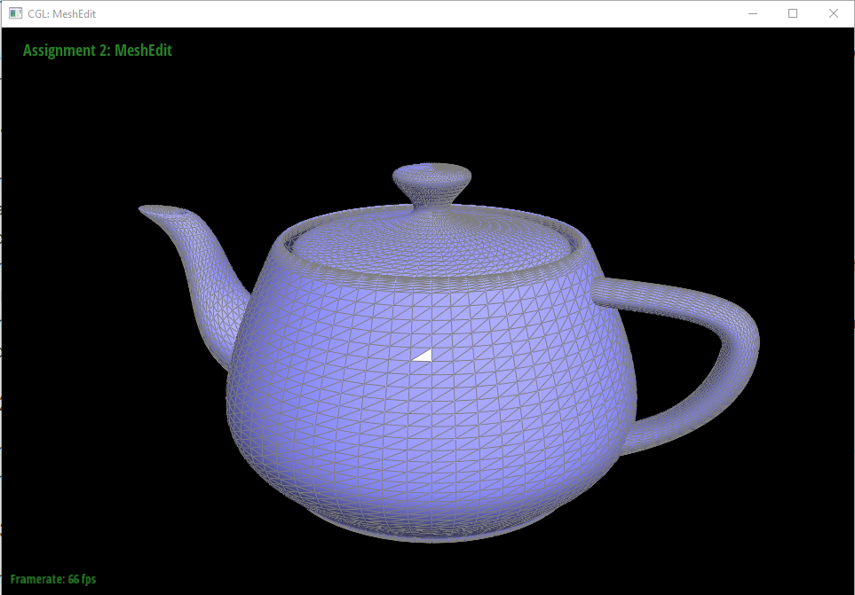
For the core functionality, i.e. BezierPatch::evaluate, we are given two control parameters u and v instead of a single t, as well as a
"control matrix"(represented by a two dimensional vector) to work with. Suppose our control matrix is of sizen x m, then we can treat each row as a list of control points and evaluate a single Bezier curve out of it with parameter u. Repeating this process (as we have done in task 1) for each row will give usnsuch curves at u. We then feed these points into BezierPatch::evaluate1D with parameter v and the returned point is the location of our Bezier surface at parameter u, v.
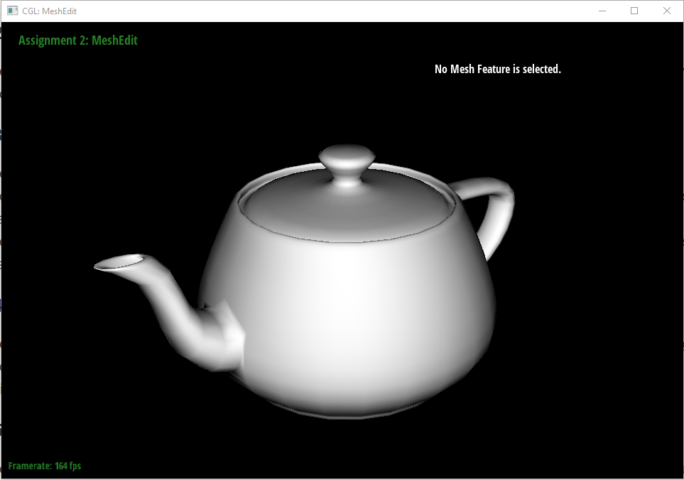
Screenshot of teapot consist of Bezier Surfaces
Task 3: Area-Weighted Vertex Normals
In this task, we try to find the normal of a vertex based on the normal of each incident faces weighted by their areas. We traverse the faces in a loop starting from the vertex's direct halfedge h. Inside the loop, we first obtain the face normal by calling h->face()->normal(), then we collect the positions of the three vertices a, b, c (we access the other two vertices with h->next()->vertex() and h->next()->next()->vertex()). The face area is then computed with the norm of cross product (a - b) X (a - c). Finally we move to the next face at the end of a loop with h = h->twin()->next() (terminate when we return to the original half-edge). The weighted normal in each loop is summed up and normalized at the end to speedup execution.
Screenshots of shading with & without vertex normals

Task 4: Edge Flip
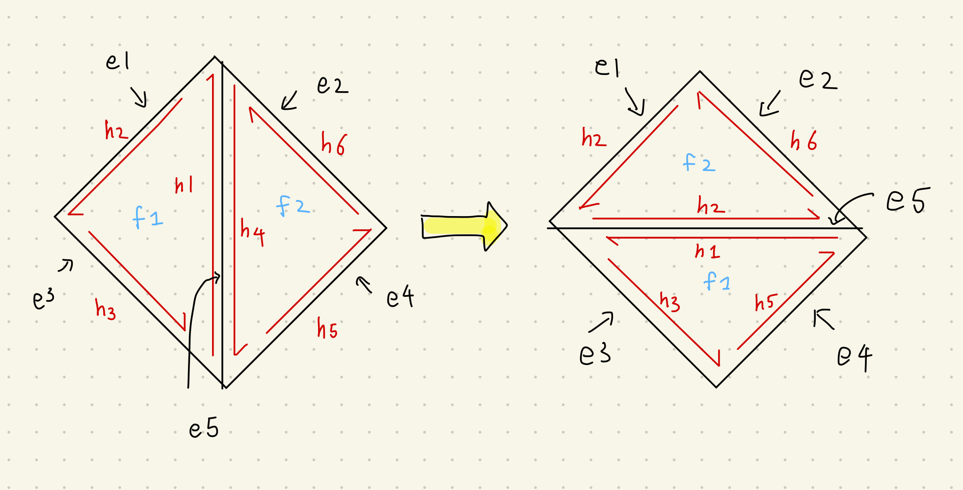
The implementation of edge flip is demanding as there are some design choices to make that would have impacts on later parts. The general flip operation is illustrated in the above image. More specifically, if the original mesh looks like the left geometry, then the left face is gonna be the down face and the right face be the up face after edge flip. In the code's level, the above is achieved in below steps.
Firstly we check if the edge is a boundary one, which is a corner case that I didn't implement and support.
We check that if the "edge vertices" (two vertices of e5) have their half-edges to be e5. If yes, we must change their pointers. Similarly we do a check for f1 & f2 and change their half-edge pointers if needed.
We then notice that the next() pointer of half-edges h1 ~ h6 all change after the flip, so we set them to the right value in an order that guarantees the correctness (namely, we start from "far away" half edges such as h3 and h6).
Finally, we set the vertex() pointer of h1 and h4 to be the correct one.
My original implementation in step 2 above doesn't involve a checking process, i.e. I forcefully reset the half-edges of the vertices on two side of the flipped edge to some other ones. This is a bad move since I later used the original half-edge to store the new location of the vertex in loop subdivision algorithm. This took me a bunch of time to debug and taught me a lesson about the importance of keeping the structure's stability.
Example using edge flip
Task 5: Edge Split
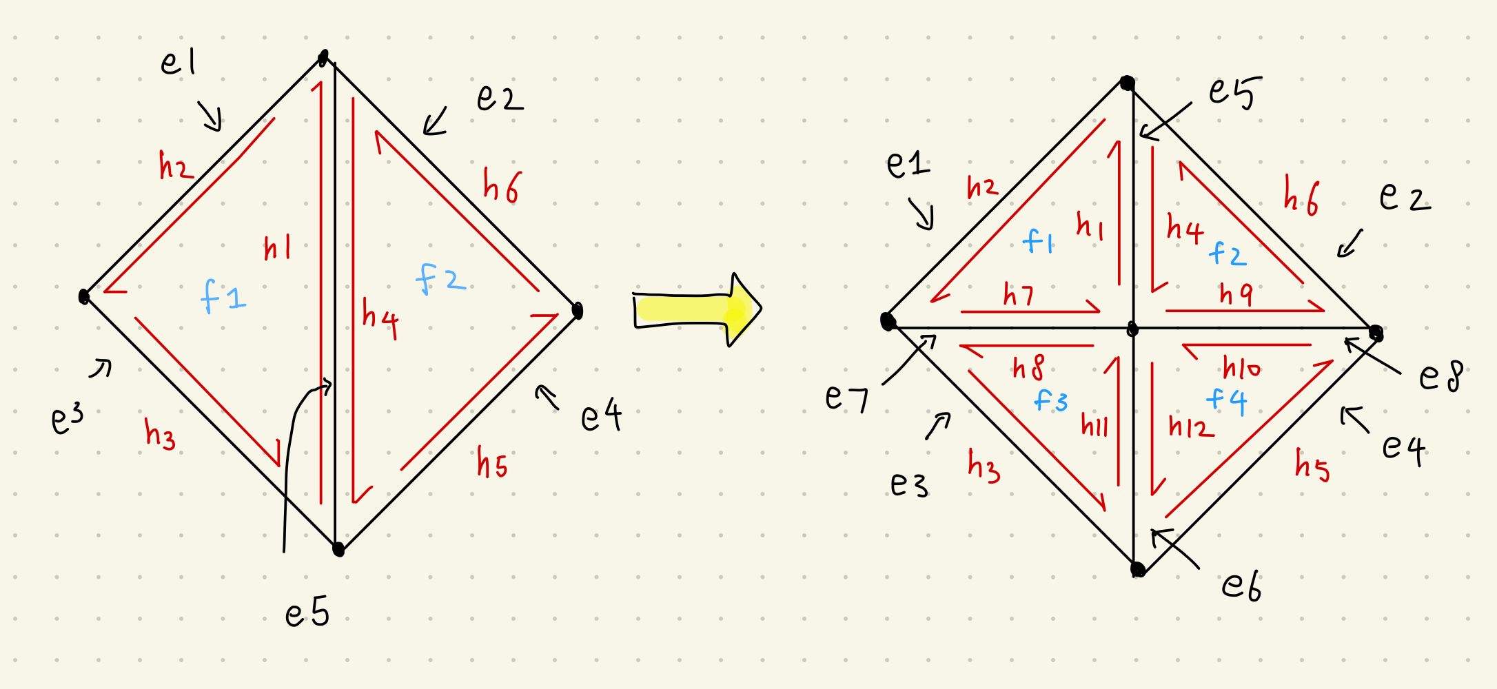
Edge split is way more complicated than the edge flip done above since it involves creating new elements and moving more pointers. Some design choices are made as well. For the integrity of the structure and the ease for later part, I chose not to delete any element. Therefore, we can see that the original faces f1 and f2 as well as edges e5 are preserved and moved to the upper part after splitting. The specific steps are as followed:
Again we begin with checking for the corner (boundary) case, which is not supported in my vanilla implementation.
We create all the new elements needed for edge split (see above image). In total, we need to create 1 new vertex (and set its position), 2 new faces, 3 new edges and 6 new half-edges.
Then comes the tedious pointer operations. We first set the half-edge pointers of faces and edges, then the vertex() of h1 to the new vertex (and the vertex's half-edge in reverse). After that, we use setNeighbors to modify all pointers of each half-edges in a similar order as in edge flip.
Example using edge flip
I became more careful in my implementation in this part since it looks really hard, so no major bugs had occurred to me. The only exception is that I once forgot to move the pointer of h1 the new vertex as described in step 3 above.
Task 6: Loop Subdivision for Mesh Upsampling
In this very last (and hardest) task of the project, I took the hint in the project specification and my implementation is the following:
We pre-compute the new positions for both old and new vertices (not yet created). For old vertices, we iterate all neighboring vertices of a certain vertex using the a similar method as the one in The HalfEdge Primer. Inside the loop, we simply weight the neighbor location with the given formula. At the end, we store the new position in v->newPosition and set the flag v->isNew = false. We do a similar step for new vertices (using a slightly different formula). Now storing this new position requires some tricks since the vertices are not created yet in this pre-computation stage. My design is to store the position in the edge of the vertex's (future) halfedge. This requires the stability of these structure's relationships and is where my bug in edge flip came from. Again we set e->isNew = false for all edges that store these new positions.
Once the last step is done, we can relax a little bit to create the vertices. Then we split all original edges and flip all edges that connect between an old vertex and a new one. Once this step is done, we have successfully subdivided each triangle mesh into four.
Finally, we can update all the vertices with their pre-computed new positions (this can be done separately but I did it in a single loop).
Once the previous tasks are finished, this part is no longer daunting for me and no major bug occurred. However, I did have interesting experience speeding up this process. Basically, I notice that new edges and vertices created are appended to the end of the internal linkedlist, which helps optimize since I can obtain the total number of original edges/vertices using int n = mesh.nEdges() and only iterate the first n items if we want to ignore newly created elements.
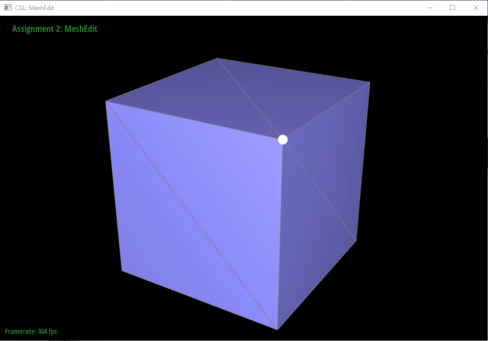
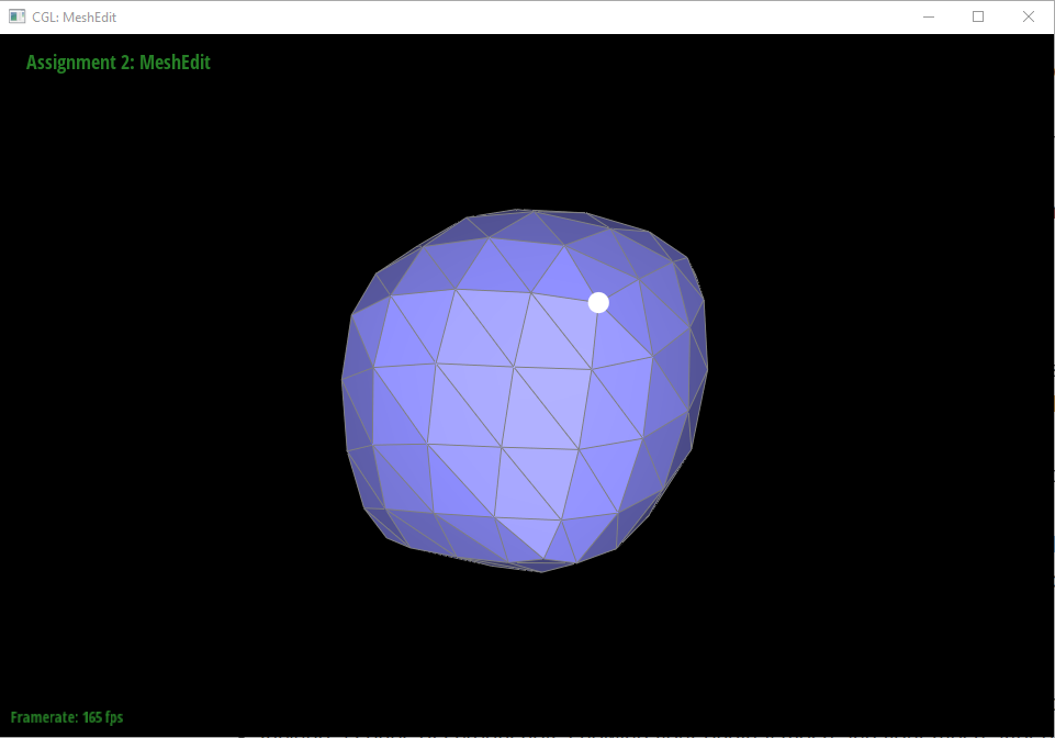
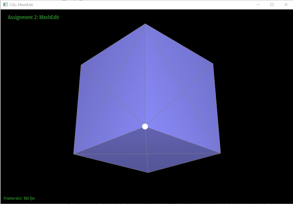
Observing sharp edges and corners
In general, the subdivision and vertex update makes the subdivided mesh smoother (at least C0 continuity) and smoother. However, sharp corners remains and is not smoothed as much. To fix this, I try to connect more neighboring vertices to the corner vertex, expecting that more vertices can "average out" more sharpness of the original mesh. (This method has its limitation since the weight (1 - n * u) is a constant regardless of neighbor amount). However, some small improvements can be observed.
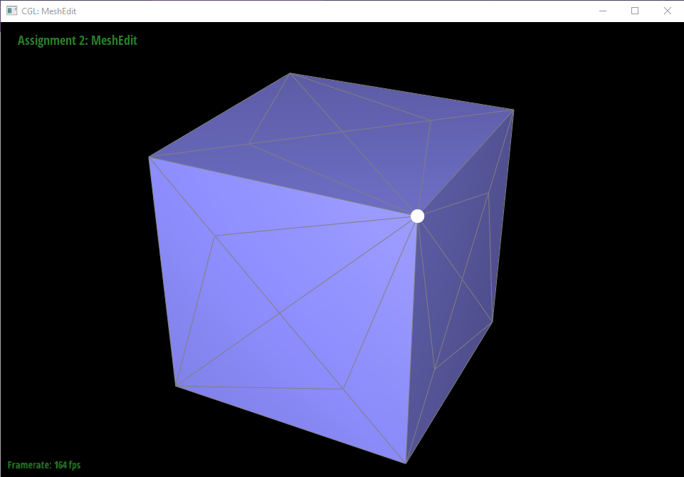
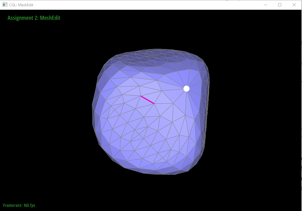
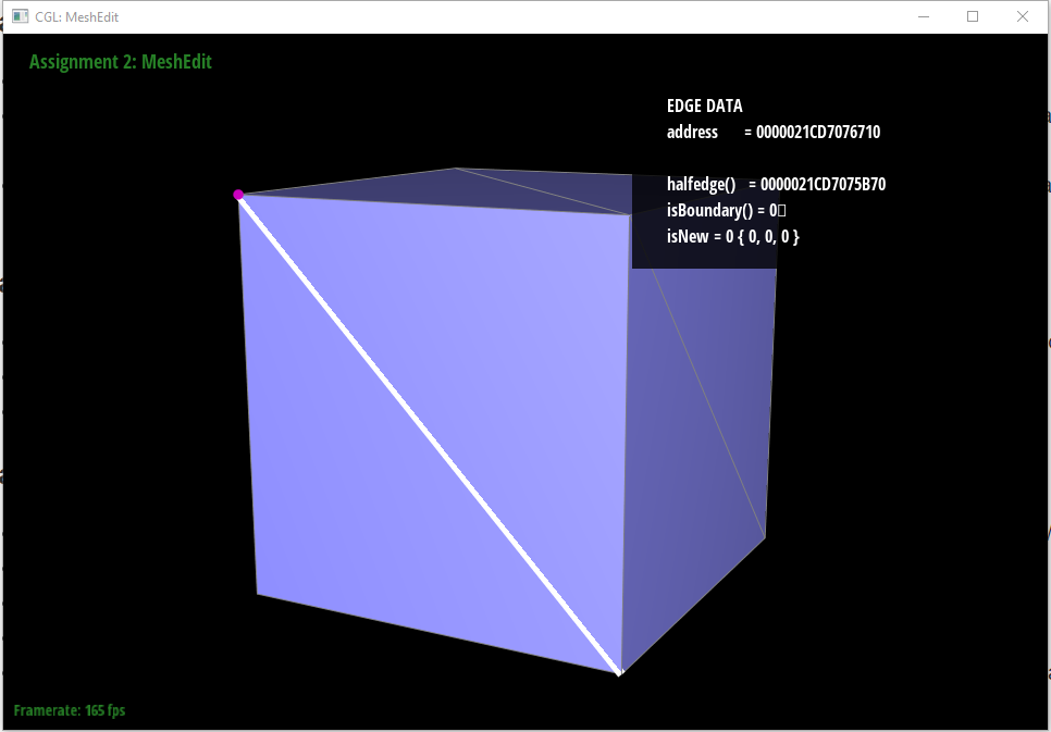
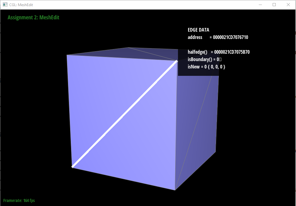
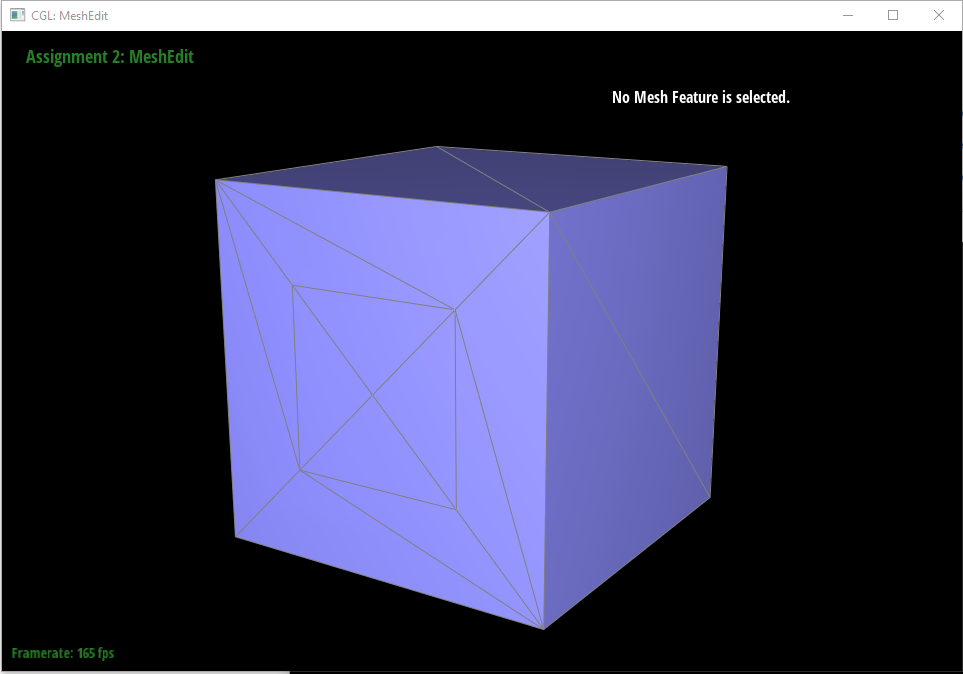
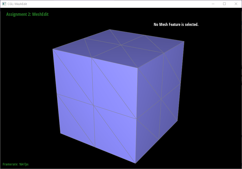
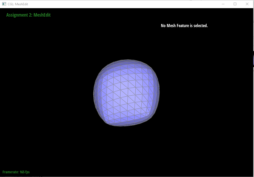
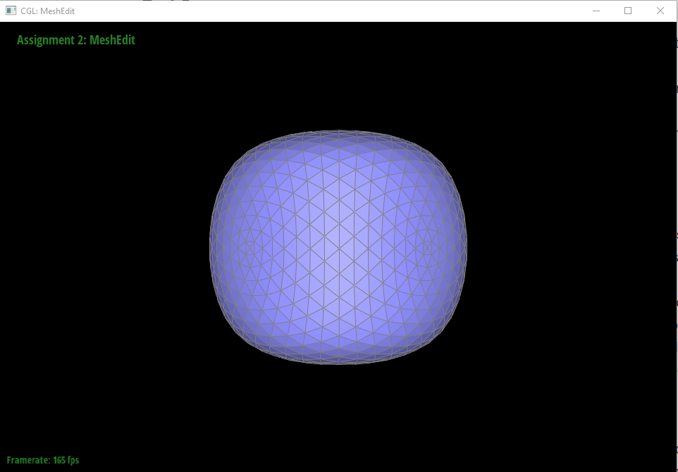
Making the cube symmetric
As we try to subdivide the cub.dae, we can easily notice that the resulting meshes looks assymetric. Taking a look at the raw cube mesh we notice that on each face there's only one diagonal edge connecting a pair of vertices. This pair of vertices then have more neighbors than the other pair and is thus weighted differently in our updating formula. To resolve this issue, we can simply do an edge split on each of the six faces so that the other diagonal edge can be connected as well. This will perfectly make the upsampled mesh symmetric, as shown below.
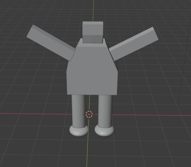
Task 7: Design and Edit Your Own Mesh!
I learned and enjoyed creating my own mesh using blender. However, possibly due to the lighting issue, my .dae file cannot be loaded into our program. Though failed, I still wanna show my work here for memory.
Made with ❤ with Bootstrap, by Star Li (listar2000@berkeley.edu) My Website