Overview
In this project, I simulated a piece of cloth under some constraints. For example, I simulated how the cloth behaves when two points of it are pinned against a wall and how it reacts when it falls onto nothing or onto another object. Since we render this based on physics, we can change the animation of the cloth such as gravity, damping, and density. In the first part of the project, I first have to build the cloth by using a grid of point masses and springs. Then, I added physics of motion to it by using Verlet integration. Finally, I added shaders to add more visual effects to the cloth.
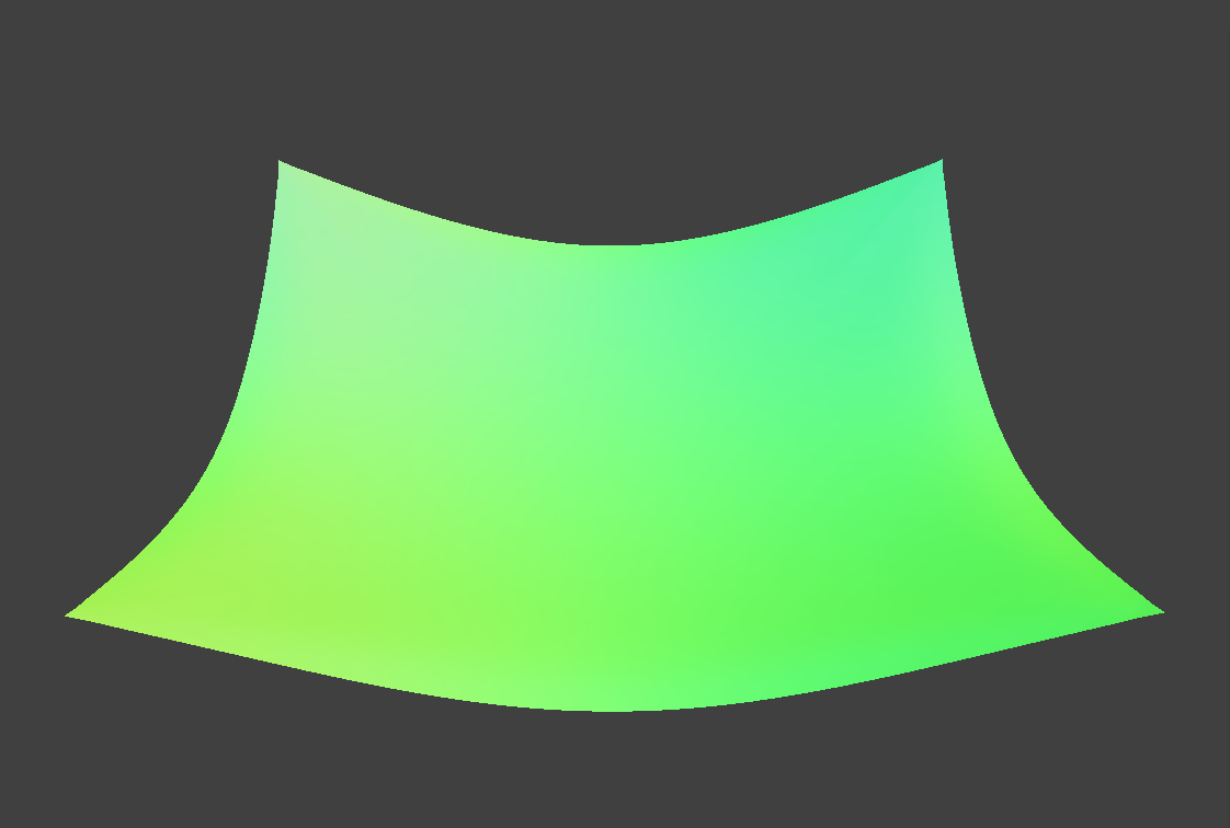
Part I: Masses and springs
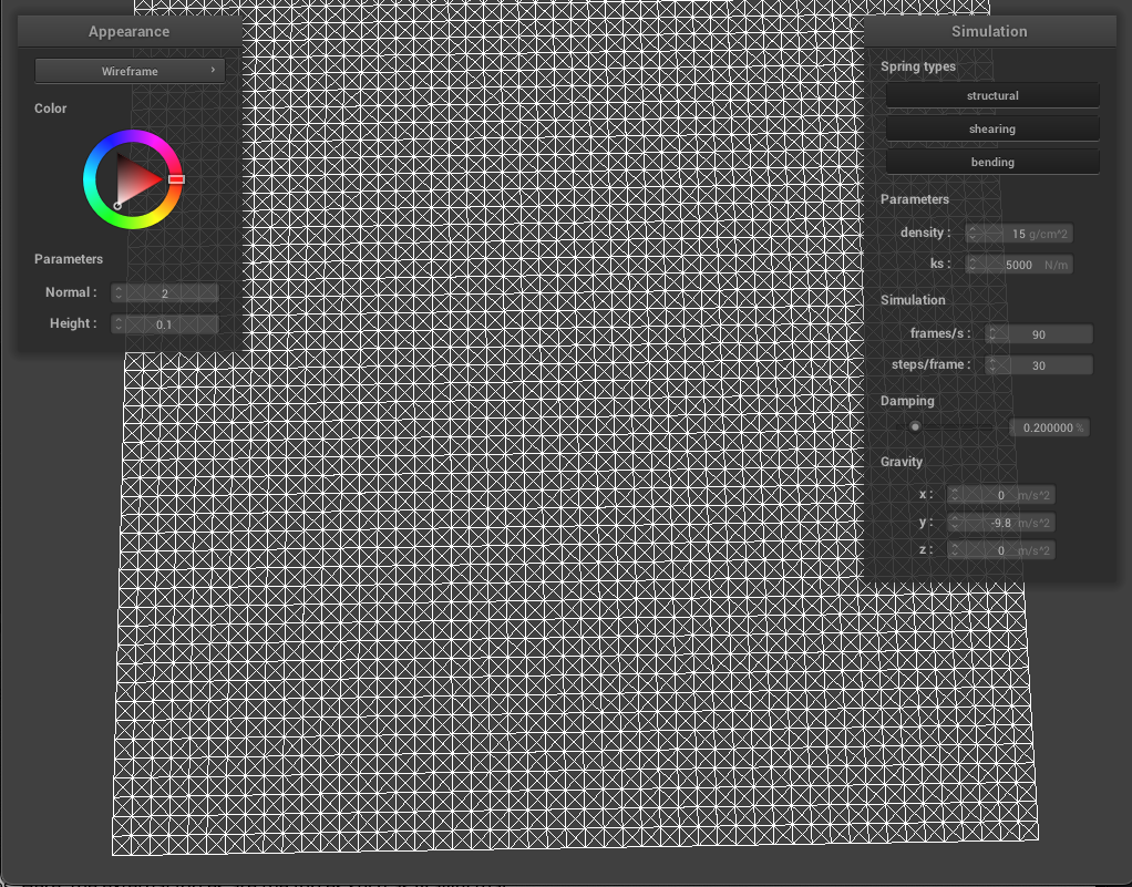
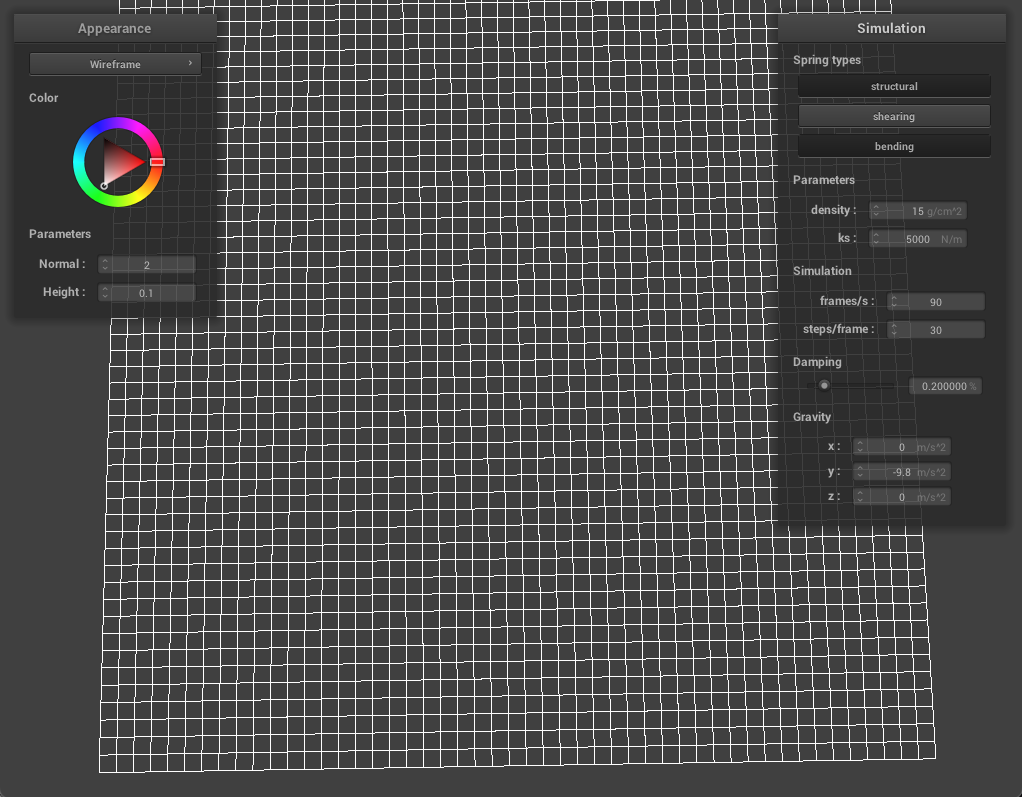
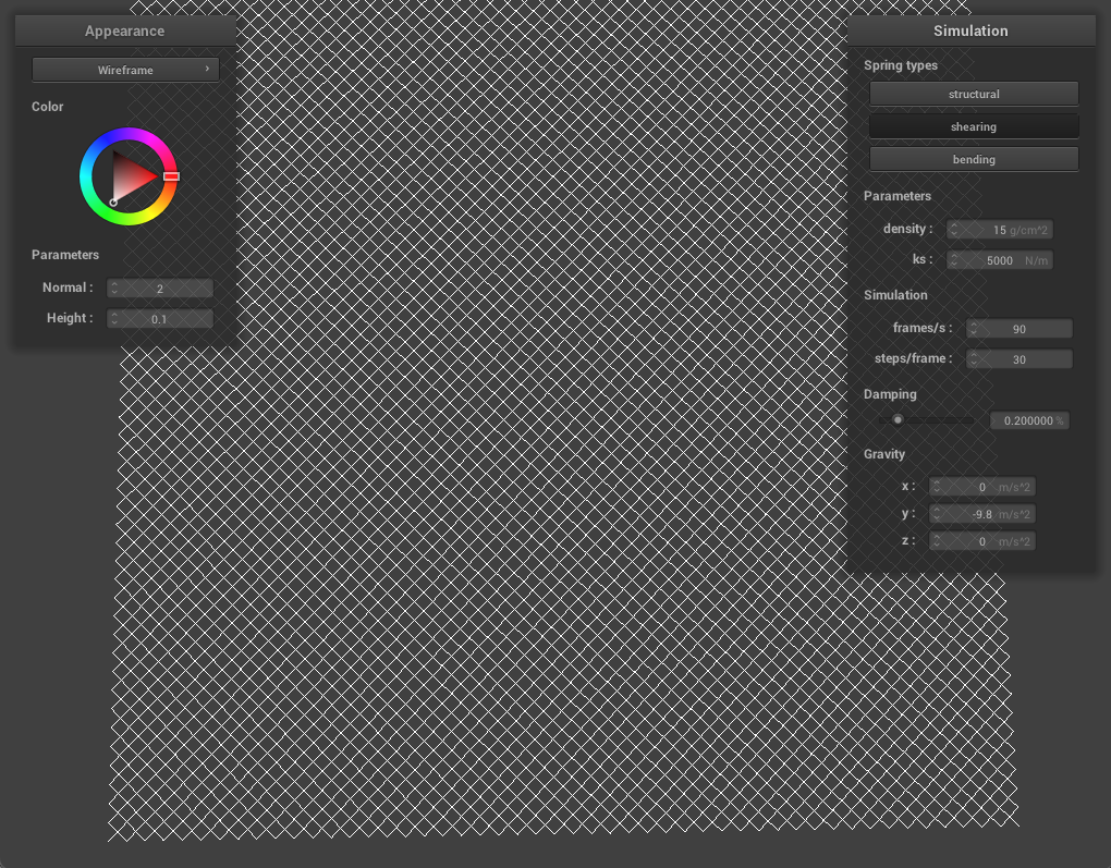
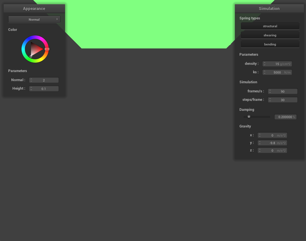
In this part, we created a grid of point masses and springs for a sheet of cloth by dividing the cloth up into evenly spaced point masses and and then connecting nearby masses with springs. Essentially, a cloth is made up of point masses each connected to other point masses via springs. We use 3 different type of springs: structural, shearing, and bending to further constrain the cloth and to prevent any deformations the cloth may have.
|
|
|
Part II: Simulation Via Numerical Integration
After setting up a system of point masses and springs, we can now simulate motion by applying the forces on our cloth's point masses to figure out how they move from one time step to another. First, I compute the total force acting on each mass. Here, we have external forces which are the parameters we can change in real-time during simulation such as gravity and internal forces which are the forces from the spring acting on the point masses. After computing the force acting on each point mass, I then used Verlet integration to compute each point mass's change in position. Verlet integration is used instead of other methods such as Euler's method because it is fairly accurate and easy to implement since we can approximate our current velocity by change in position (current position - position from last time step). We also add damping to help simulate loss of energy due to friction.
Then, to prevent the springs from being deformed during each time step, I implemented a feature based on the SIGGRAPH 1995 Provot paper which constrains each spring to be at most 10% of its rest length and perform any corrections to the point masses connected by that spring if needed.
|
|
|
|
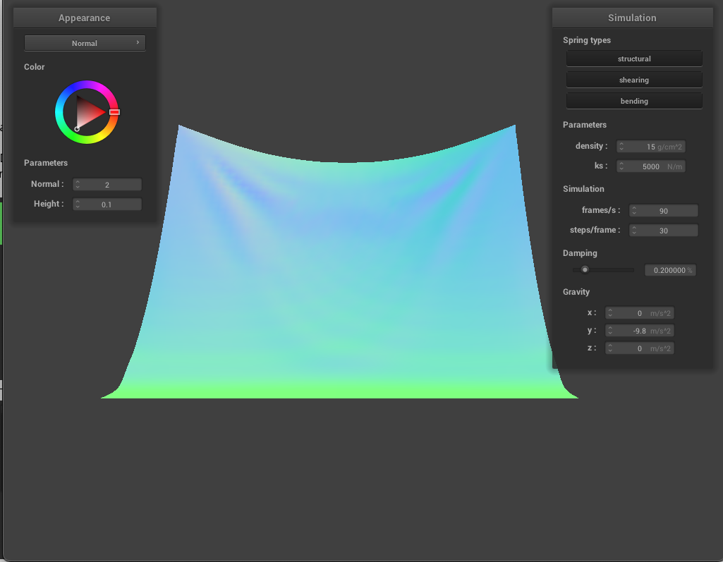
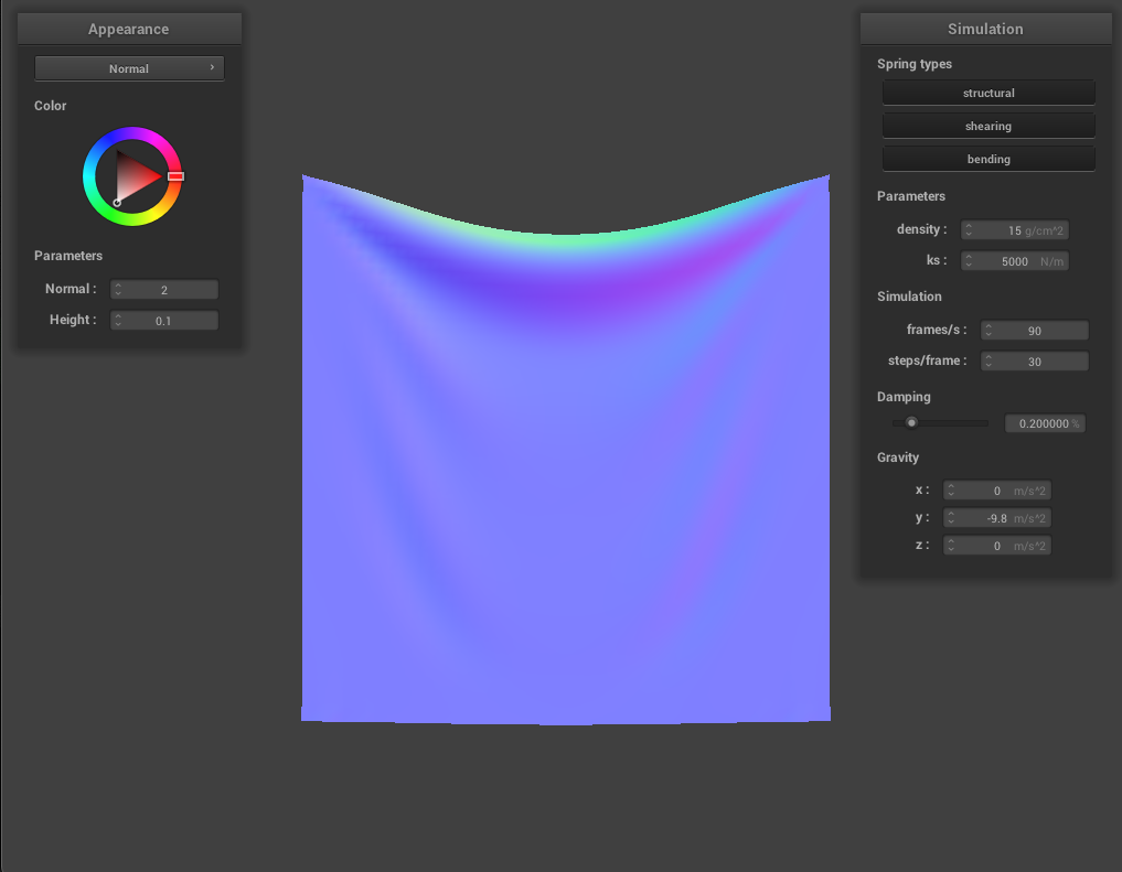
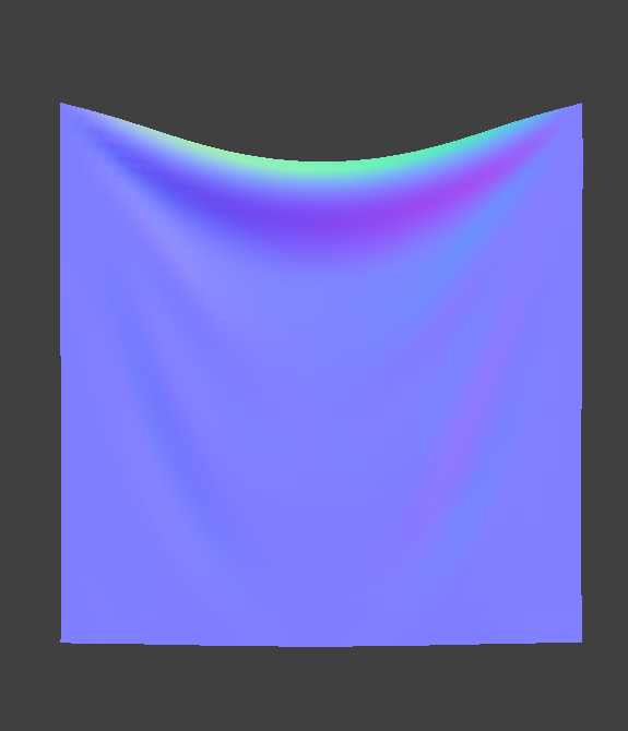
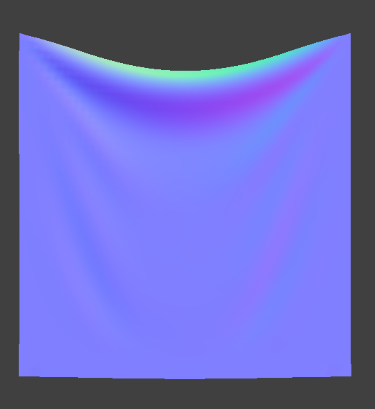
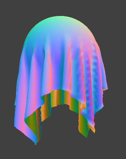
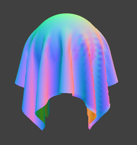
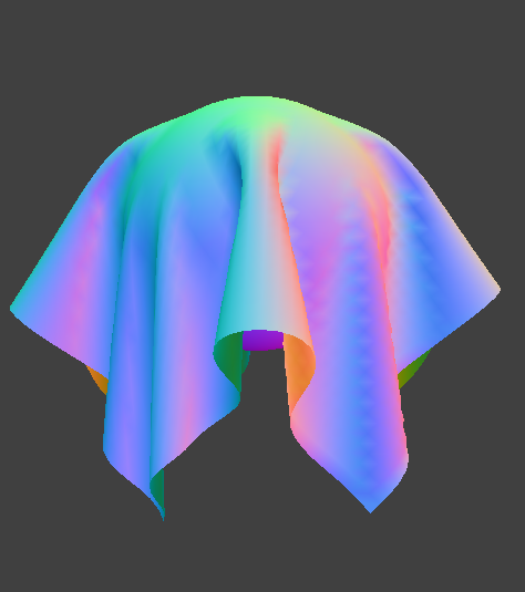
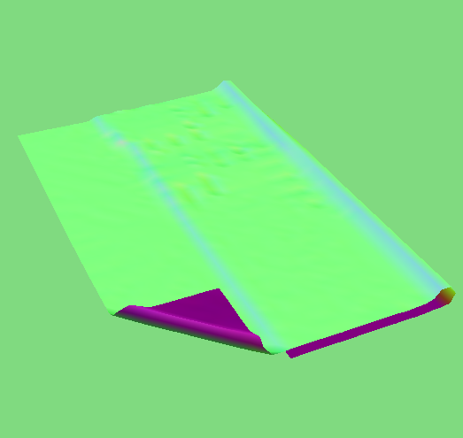
A high ks essentially means the cloth is more stiff and therefore, it doesn't hang as low as a cloth with low ks. With low ks, the cloth hangs lower and has deeper creases.
|
|
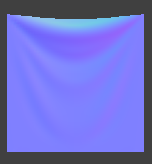
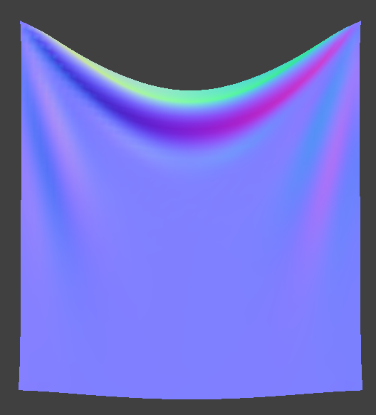
A higher density means the cloth is heavier and therefore, it hangs lower due to the weight. There are also more folds at the top, middle part. With lower density, the cloth is lighter and sags less and there are less folds at the top, middle part.
|
|
With a higher damping percentage, the cloth falls slower and there are less ripples and bounces as it falls. On the other hand, a lower damping percentage such as 0% makes the cloth fall really fast and makes it swing back and forth. In addition, there are more ripples and bounces as it swings. This makes sense as the damping percentage controls how fast the springs lose energy; with a higher damping percentage, the springs lose their energy faster and therefore, the cloth does not ripple and bounce as much as a cloth with a smaller damping percentage.
Part III: Handling Collisions With Other Objects
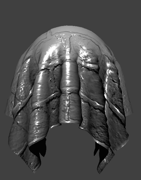
After implementing how different forces act on the cloth, we implemented how our cloth behave when interacting with other objects and in this case, with planes and spheres. Essentially, with any type of object, we check if each point mass is inside the object and if so, we adjust the point mass's position and ensure that it stays just on the surface of the object. If the point mass intersects/is inside the object, I compute the surface point of the intersection as the projection of the point mass position to the surface of the object. Then, I compute the correction vector to update the point mass's last position to be the surface point. The point mass's new position is then its last position added with the correction vector which is scaled down by a friction factor.
|
|
Increasing ks results in less wrapping of the cloth around the sphere while decreasing it makes the cloth wrap more around the sphere as well as have the edges drape more.

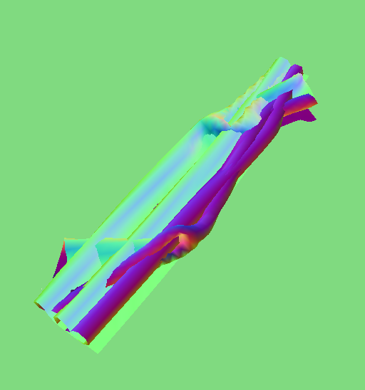
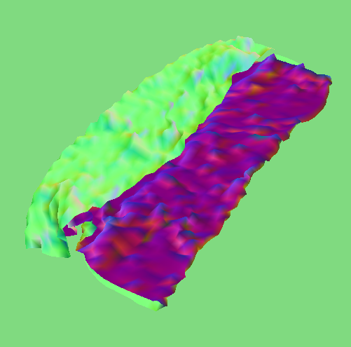
Part IV: Handling Self-collisions
In part III, we only accounted for collisions with other objects but not with the cloth itself. There can be a scenario in which the cloth falls onto itself and without self-collisions implemented, we see the cloth clipping through itself and other strange behavior. In order to prevent this from happening, we do spatial hashing. At each time step, we build a hash map that maps a float to a list of point masses; the float represents a 3D box volume and the list of point masses correspond to the point masses in that 3D box volume. After this hashmap is set up, we just have to check each point mass in each 3D box volume and apply any corrections to any point mass that are too close to each other. Using spatial hashing is more efficient since we do not need to loop through all pairs of point masses, compute the distance between them, and check if they are within some threshold distance apart. The hash map cuts down the number of checks we have to do!
|
|
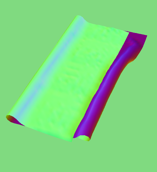
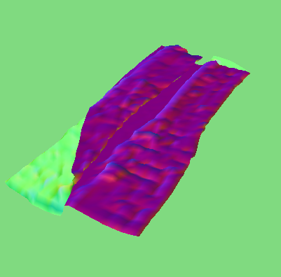
Increasing and Decreasing Density:
Increasing density of the cloth results in more folds in the cloth and therefore takes longer to uncurl. On the other hand, decreasing density leads to less folds and therefore takes less time to unfold.
|
|
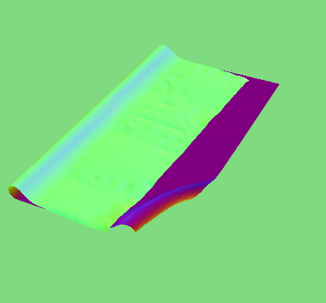
Increasing and Decreasing ks:
Increasing ks results in faster uncurling of the cloth. This makes sense since the cloth is more stiff, it quickly straightens out. Decreasing it takes longer for the cloth to uncurl since it is more flexible.
|
|
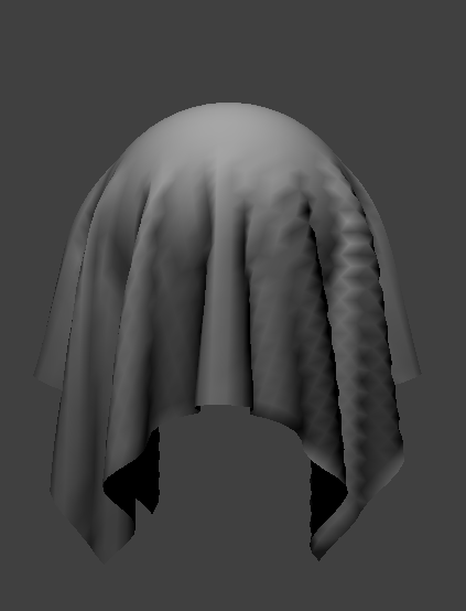
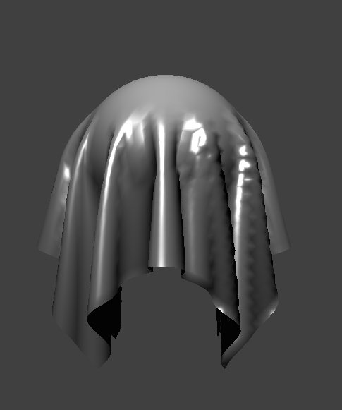
Part V: Shaders
After implementing the physics of the cloth, I added shaders to our cloth. I added 5 shaders: diffuse shading, Blinn-Phong shading, texture mapping, displacement and bump mapping, and finally mirror reflections. To write the shaders, I used a GLSL shader. A shader program such as GLSL shader works by running in parallel in GPU instead of the CPU. I used two shader types: vertex shaders and fragment shaders. Vertex shaders apply transformations to vertices such as their positions and write the final position of the vertex to `gl_Position` and forward this data to fragment shaders. The fragment shaders compute and write a color into `out_color` which then is the final result that we see as a visual effect in our cloth simulator.
The diffuse shader is a shader that is independent of the view direction.
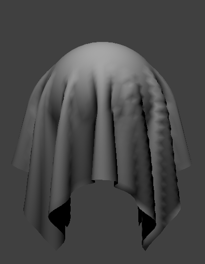
The Blinn-Phong shading model is an extension of the diffuse shader in that it takes into account of view direction. The model adds ambient lighting and specular reflection in addition to the diffuse lighting from the diffuse shader. The model now has additional k constants that can be adjusted; they represent the weights we can give to each lighting component of the model. The Ia term is the value of the ambient light and the p value controls how large our specular reflection is.
|
|
|
|
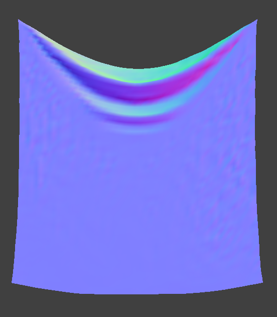
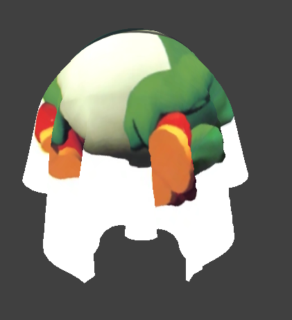
Texture mapping is straightforward. We map a texture onto the objects in our scene by using the built-in function `texture`.
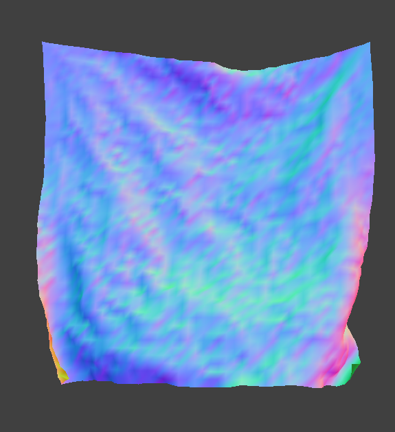
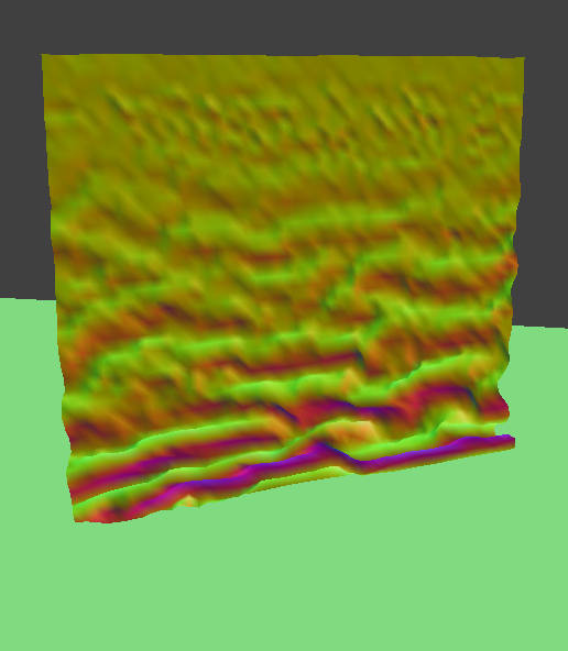
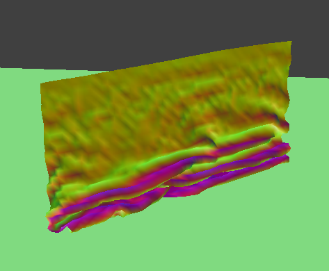
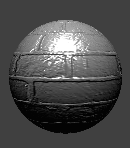
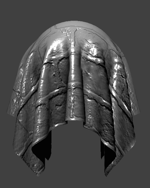
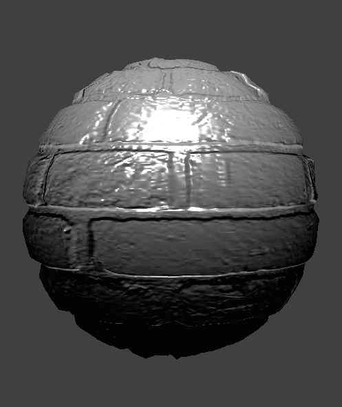
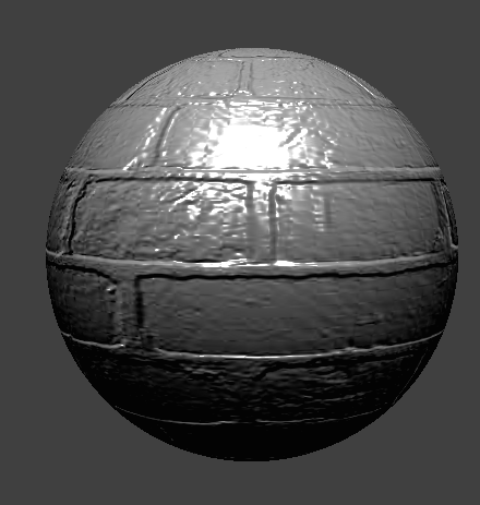
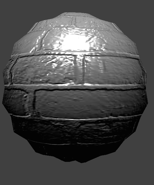
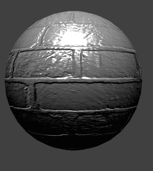
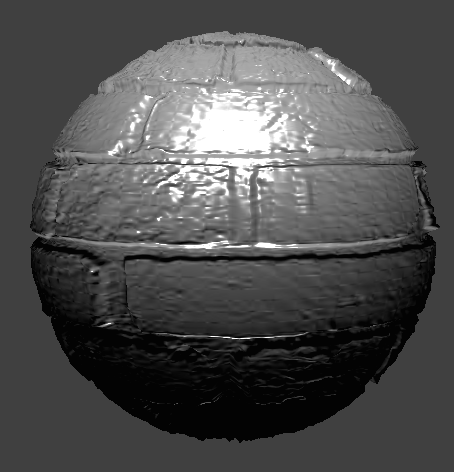
Displacement mapping modifies the actual geometry of an object by displacing its vertices based on a height map. On the other hand, bump mapping does not change any actual geometry but rather simulates the appearance of surface detail by altering the surface normals of the object. Below you can see distinctly see that bump mapping does not change the geometry; it does not create the deeper lines that we see with displacement.
|
|
|
|
Using the following flags such as `-o 16 -a 16` changes the resolution of the rendered spheres. -o [number] controls the vertical resolution, and -a [number] controls the horizontal resolution. It is hard to tell if the resolution of the sphere improved the visual look with bump mapping but with displacement mapping, we can see that the sphere is more realistically rendered with higher resolution.
|
|
|
|
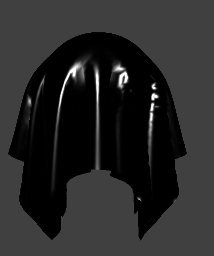
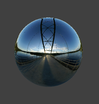
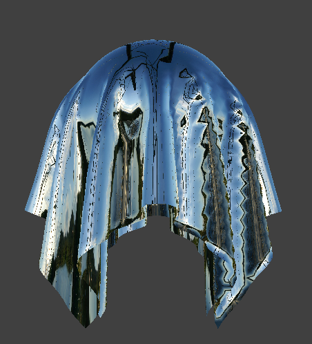
Mirror shading is similar to texture mapping except we needed to trace a ray to determine the reflected direction. After this, we simply sampled from the environment map.
|
|
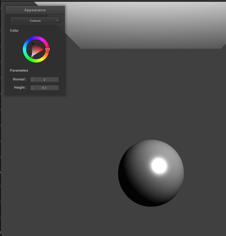
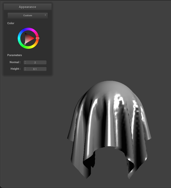
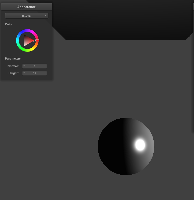
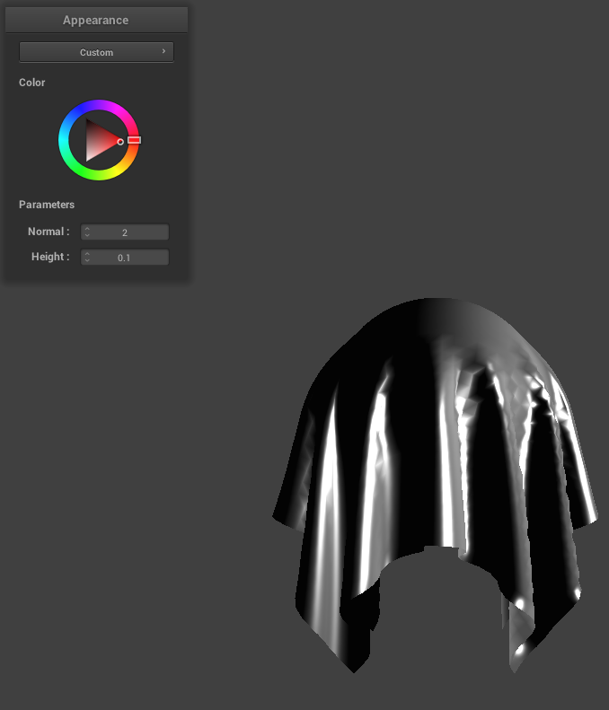
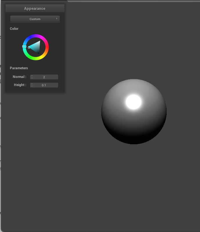
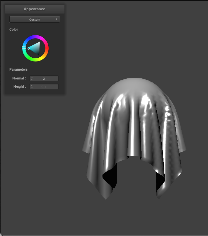
I also added a custom shader. I noticed that in the Blinn-Phong shader, light source angle cannot be changed so I implemented this in this custom shader. I realized that I could just use the color wheel to adjust the angle of the light source. Since this is already in clothSimulator.cpp as `u_color`, I added this to the custom shader's fragment file and used it to determine light direction. Instead of the vector pointing from the current vertex that is being shaded towards the light position, we simply use `u_color` and normalize it. With this implemented, the value in the color wheel chosen by the user will determine the direction of the light source.
|
|
|
|
|
|